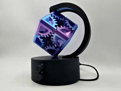
Rotating Gear Lamp Display


Print Profile(3)


Bill of Materials


Description

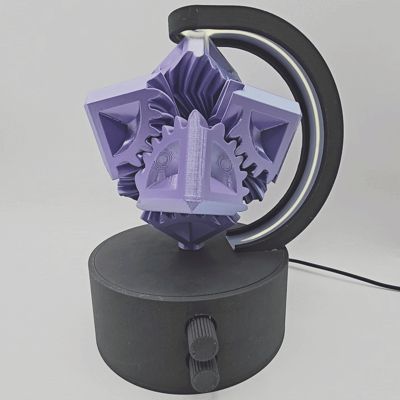
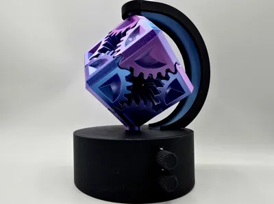
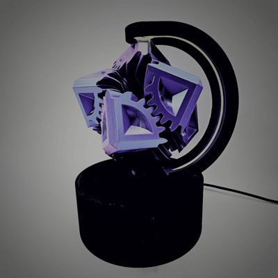
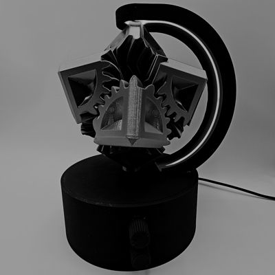
Available exclusively on Makerworld - Featuring automatic rotating gear cube with adjustable speed and LED lamp with adjustable brightness - USB powered suitable for any home or office space
Mesmerizing & Elegant
This passion project requires mostly parts available on Makerworld and Amazon, listed below - Simple instructions with photographs to assist building after printing, small amount of soldering is ideal
BOM (Parts required)
Makerworld Parts
-ZH038 - Maker's supply elecronics bundle (1PCS) - ZH038
-KA009 - 300x1mm COB LED Strip Light (1PCS) - KA009
-AA149 - M2x4 SHCS Machine Screw (20PCS) - AA149
-AA144 - BT3X12 Self Tapping Screw (2PCS) - AA14 (or similar 3mm screws, minimum 12mm)
Additional Parts (Amazon)
-1x SH1 2P Connector (Available in many kits - I used this one here on Amazon)
-1x DC 12V Reduction Motor 25RPM - (There are many similar however I used this exact one here on Amazon)
Any soldering iron and solder
Superglue
Small heat shrink tubing and heat source (non essential)
cable ties (non essential)
Screwdriver to suit required screws
Grease/ lubricant
Once you have these parts and I ready to print I recommend these settings
-Print in any color choice but the transparent arch cover which must either be transparent or Bambu Glow PLA (pictured)
-Support for PLA is greatly recommended on the arch to improve quality of overhangs
-Silk can be great on the gears but I recommend a print speed of 60mms
-Regular PLA recommended elsewhere
-Regular supports on build plate only (except on for top piece)
Once printed please ensure all support interface is cleaned for the print
Building Instructions


Glue the 2 alignment pins into 1 side of the centre piece

Glue the second centre piece onto the first centre with alignment pins

Connect the wires by number and thread the COB LED through the base middle slot as shown
Then push the dial covers onto each potentiometer

Push the COB LED into the slot in the middle of the arch as shown

Push the transparent arch cover into the slot on the arch and slide around to cover the COB LED

Ensure the whole arch is covered and the hole aligns at the top (pictured above)

Use 2x4 screws to screw the power distribution board and 2x potentiometers into the shown positions with their connectors facing up

Tuck the wires behind this post

Pull the USB cable through the back like shown

Then loop the opposite end of the USB cable through the side inside the base as shown above

The USB cable needs to feed through exactly as shown above

The USB cable can then be plugged in as shown, it should look just like shown above, you can also add the wire cover here

Now we need to connect 1x - SH1 2P connector to the motor, here I soldered the red and black cables and used heat shrink - the connector was push fit (you need to test the positive and negative orientation)

The motor can the be installed in this position and connected as shown (now would be a good time to test the motor using the USB cable)

Push the first cog onto the motor and then install the motor clamp using 3x12 screws (longer screws will work however & self tapping screws recommended, although I used machine screws from a spare P1S hotend)

Add grease to the last 2 cogs (very little required)

Add the last 2 cogs as shown

Add the first cog with the insert through the long arm on the centre

I also recommend some grease inside the gears

Add the second gear with the top pin onto the centre opposite the first gear

Add the third gear in this orientation (there are 2 types of gears, note the pattern is opposite to the corresponding gear)

Continue pushing the gears into the cube in their correct positions shown above

Here is the final cube and base complete

Slide the COB insert into its sleeve on the top as shown (you may wish to tape here to prevent sliding, but not essential)

Test fit the top into the base as shown

Test fit the arch into the top and base - DO NOT GLUE YET - ensure the COB LED is pushed through fully into the base

Note the orientation of the insert of the cog seen through this hole and align with the pin on the bottom of the gear cube (gear 1 facing down)

Now align the top gear pin with the pin on the arch and carefully push together

Make sure the gears aligned into their holes - Note the arch is still loose at the bottom, allowing freedom to align before gluing

Add small amounts of superglue into the 3 slots as shown here to glue the arch into the base while the cube is still fixed in the centre (use small amounts of glue as to not spread to much glue) NOTE TESTING BEFORE GLUING IS ADVISABLE TO ENSURE THE MECHANISM WORKS - JUST HOLD TOGTHER BEFORE GLUE

Once glued, your cube is now ready (you can remove the top from the base easily in-case you need to make internal adjustments)
Enjoy your gear cube is now ready -any assistance required I'll be sure to assist as best as possible & I hope the instructions are helpful enough to complete this beautiful project
License
You shall not share, sub-license, sell, rent, host, transfer, or distribute in any way the digital or 3D printed versions of this object, nor any other derivative work of this object in its digital or physical format (including - but not limited to - remixes of this object, and hosting on other digital platforms). The objects may not be used without permission in any way whatsoever in which you charge money, or collect fees.
Comment & Rating (65)