
N Scale Train Trestle Display




Print Profile(4)


Bill of Materials


Description
Summary
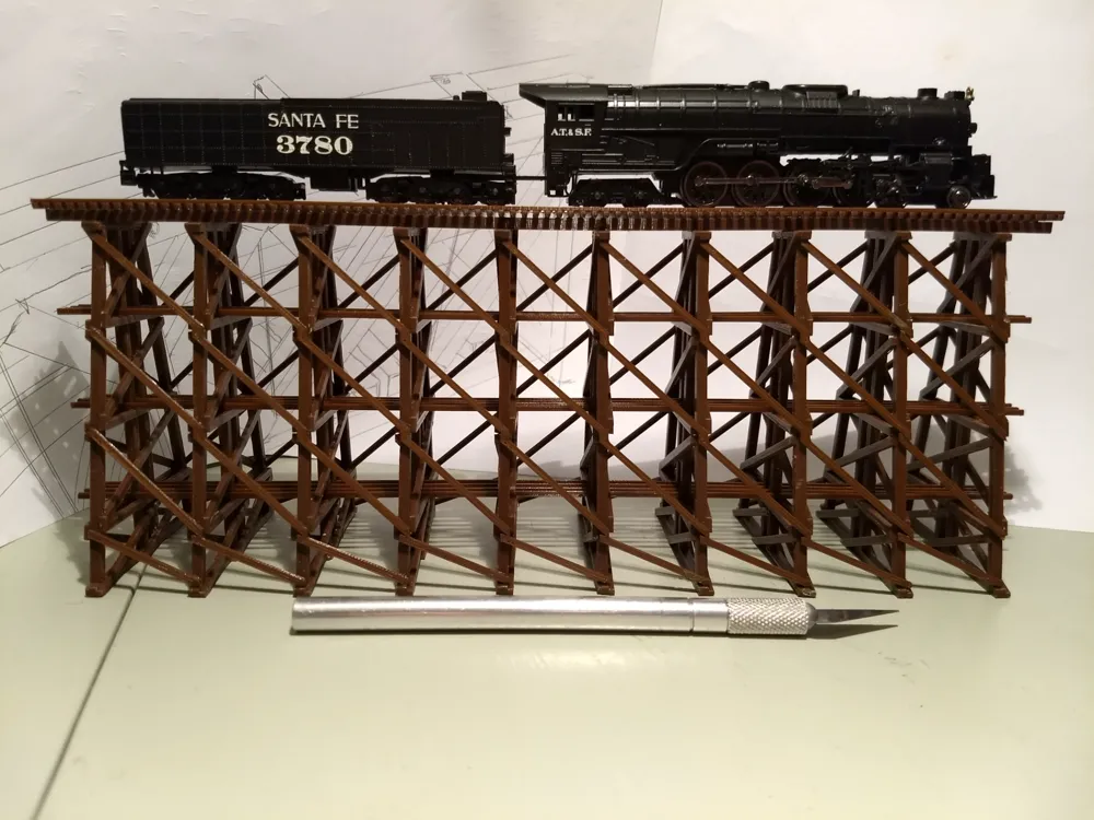
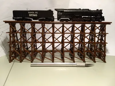
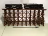
I put together these trestles to use as display stands for N gauge engines. They are about 4 inches tall. The larger trestle is 267.7mm (10.5 inches) and the small trestle is 127mm (5 inches) long, but they can easily be made to any shorter length. It is loosely based on a Great Northern Railway Standard Frame Trestle design that I found on the web.
Most of the parts can be printed without supports. Using supports with the Main Frame STLs take a while to clean up, but I found that the parts were strong and looked good when I was done. Be careful not to cut yourself when digging the support material out with an Xacto knife. Blood just ruins a good print…
After printing the SideBraces STLs, but before removing them from the print surface, I laid some wide low-tac (blue) painters tape across them, to maintain their relative position after they were removed. Make sure that you can see 1/16 in of the tops and bottoms of the SideBraces after the tape is applied. This will make it much easier to position them when assembling the bridge.
For assembly I snapped the Spacer Jigs on to the 5 Main Frames. I could have made the gaps in the Spacer Jigs a little wider, but I wanted them tight. I found that I needed to file the Spacer Jig gaps wider, and to file the sides of the Main Frames thinner, so the Spacer Jigs did not bend when they were snapped on. I made 4 Spacer Jigs. Once I had them holding the top, bottom, and one side of the Main Frames, I attached the SideBraces. I used a Glue Syringe (See more below) to apply drops of Acrylic Cement to tops and bottoms of the Side Braces then fitted the taped SideBraces to them. I then removed the tape, and put a drop of cement on each if the intermediate joints.
After the SideBraces were attached to one side, I removed the Spacer Jigs from the other side, and used the technique described above to apply the SideBraces to the opposite side.
I redesigned the Spacer Jig when I made the 10.5in trestle, because the old jig was a pain to use. The 10.5in jig is much easier to use, but the assembly process is the same.
The Bridge Top 2 part was then cemented (cross braces up) to the top of the Main Frames. Notches in the Main Frames align the Bridge Top 2 in the lengthwise direction. The cement works really fast, so I just eyeballed it to center it widthwise, and held it until the cement had taken hold.
I then added the Runners. Tilting the assembly to one side, glued in half the Runners, then tilting the other way, added the rest. I used a pair of scissors to cut off the ends so they would be equal length.
I used the rails from Atlas Code 55 Flex Track for the main and safety rails. If you live in the Portland Oregon area, I would highly recommend Tammies Hobbies (https://www.tammieshobbies.com/). This is a local store for me, but their store prices for train related stuff is competitive with anything that I can find elsewhere on the internet. But enough with the pitch.
Cut 4 rails and file to length with a fine file. Cut the corners on the end of the track to make it easier to slide in the Bridge Top 1 part. The rails fit very tight. I pushed then in just a little bit, then took the bed of my printer up to 70 degrees C and laid the part with the rails partially inserted upside down, to warm them up. I then gripped the rails with a needle nosed pliers a 1/2 inch from the part and slid them in a little farther. I repeated the warming and short press steps several times to get the rails full inserted. Once this is done, the Bridge Top 1 part can then be glued to Bridge Top 2 part.
To glue the parts I purchased the Acrylic Cement and Applicator Syringe from Amazon.
Glue Applicator Syringe:
https://www.amazon.com/Applicator-Syringes-Needles-Refilling-Measuring/dp/B07YB8SYCG
Use the smallest diameter needle with the Acrylic Cement
Weld-In 3 Acrylic Cement: This stuff works better than SuperGlue for PLA.
https://www.amazon.com/Weld-Quarter-Formula-Acrylics-Adhesive/dp/B0FNY9KQW6?th=1
24/8/16 - Initial Release
26/6/4 - Added A1-Mini and P1S Small Trestle Print Profiles, and a P1S Large Trestle Print Profile.
License



Comment & Rating (21)