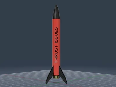
Mid-Power Model Rocket - Thrust Issues


Print Profile(1)
Description
Description
This kit will provide all the necessary 3d printed parts to create your own D/E/F motor powered amateur rocket. The design is built around a 15" x 2" (381mm x 55mm) cardboard shipping tube which provides a strong, inexpensive, lightweight base. Parts should be printed in the orientation in the .3mf file, with supports only necessary for the tail fins. It is recommended that parts be printed in PETG at .16mm layer height with a 0.4mm nozzle. The fins should also be printed using arachne wall generation and seam generation set to back. PLA Aero can be used for the fins if you have the patience.
Assembly
Once all parts are printed, install one of the M3 eye hooks through the hole in the nose cone plug, securing with an M3 nut, and screw the plug into the nose cone until flush. It is recommended to apply CA glue to the threads once you have fit checked everything.

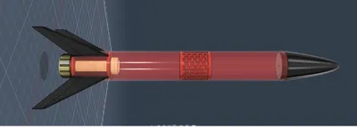
The tail fin and motor mount assembly can be built by applying epoxy to the inside of the male portion of the motor retainer and inserting the the 29mm motor tube. From there, slide one of the printed motor spacer rings onto the engine tube with the grooves facing upward it should be flush against the motor retainer. Next, the fins can be added, with the fin tabs fitting in the grooves of the retainer ring. Finally, add the second retainer ring, grooves down, ensuring the grooves mesh with the top of the fin tabs. Final assembly should resemble the picture above. Apply epoxy to all the butt joints between the motor tube, fins and centering rings. The female portion of the motor retainer should be saved as it will need to be screwed on firmly after a motor has been installed to ensure it is not ejected instead on the nose cone during usage.
While waiting for the epoxy to harden, place the tail fin alignment jig on the shipping tube and mark the slots with a sharpie. Remove the jig and cut the fin slots out using a dremel or x-acto knife. The slots should go all the way to the bottom of the tube. Install the tail assembly up from the bottom until the lower centering ring is flush with the bottom of the shipping tube.

Next, attach the second M3 eye hook to the center hole of the upper ejection charge baffle, again securing it with an M3 nut. Screw the upper and lower sections of the baffle onto the midsection, then apply CA glue to ensure they do not back out. Attach the shock cord to both eye screws with a strong knot. After verifying fitment, apply CA glue or epoxy to the assembled baffle and install through the top of the shipping tube. Using a bamboo skewer, slide the baffle into the tube until the top of the baffle rests about 10cm from the top of the shipping tube, as shown in the picture above.
Attach the rail buttons to the shipping tube using the included hardware and stiffen with additional CA glue or epoxy. Finally attach the parachute to the eye hook on the nose cone and insert the nose cone into the shipping container, ensuring a loose friction fit.
If desired, paint the model as you see fit, ensuring the model is primed before painting to provide a good bonding surface for the final paint. If using larger motors, it is highly recommended to stiffen the tail fin assembly by applying fiberglass fillets at the points where the fins meet the motor tube and where they meet the body tube. This should be done prior to sanding, priming and painting.
Bill of Materials
- Carboard Shipping tube (amazon.com)
- 29mm motor tube & retainer kit (estes.com)
- 3M eye hook x2
- M3 nut x2
- Shock Cord
- Recovery Parachute
- Rail Buttons (estes.com)
Flight Simulations
Below is simulated flight statistics for several available motors. Smaller 24mm motors may also be used by printing a 24 to 29mm motor adapter available here.

Comment & Rating (1)