Brio Steamworks Gantry Crane for Wooden Railways


Print Profile(2)


Description
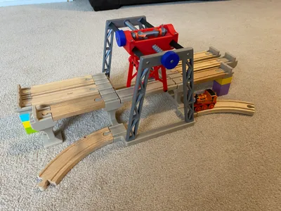
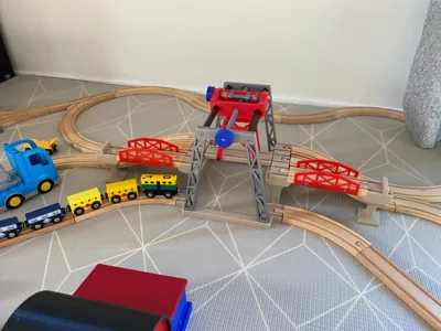
A working gantry crane for lifting broken down engines onto ‘workstands’ in the steam works.
It is the same height as standard brio bridge pieces, so ramps etc can also be joined on for open ended play.
The engines can be lifted vertically then moved horizontally and lowered into position at each location. Tracks can be added in either direction.
Update 14/01/2024 - The spring under the blue handle fatigued after quite a bit of use so I redesigned it
Pairs with the elevated buffers found here (free standing):
https://makerworld.com/en/models/127939
or here (duplo):
https://makerworld.com/en/models/127935
You'll need:
M3 x 8mm button head screws x about 26 - there is some wiggle room for smaller or larger screws in most locations if you've got different sizes laying around
50cm of relatively thin string - I used builders line - it's strong, cheap, and brightly coloured
Most parts are PLA. The springs are PETG for longer life
The 3mf sliced file contains all parts required at the correct orientation.
Most are pretty obvious - auto orient works well.
The exception is the main crane piece. The face with the threaded hole for the lead screw needs to be laid down on the print bed to make the screw socket as accurate as possible. This does mean it needs supports - I used tree supports and painted them on the large overhang as well as the top edges of the cutouts for the rotating shaft.

The rail spring slide into the crane main body before the body is slid onto the rails. The little notch on the spring clicks into the notch on the rails so check the orientation here. The notches on the rails point down.
These springs are optional if you're using the lead screw to push the crane body. If you choose to leave out the lead screw and push the crane manually they're good to make it ‘click' into the correct position above each location.

The other spring goes under the handle connected to the rotating shaft. There is a cutout to seat it into. It doesn't have to be tight. This spring adds the friction required to the handle to stop the crane unwinding under the weight of an engine.
Avoid the temptation to squish the spring before installing it - if you deform it too far it won't bounce back.

Tie the string from the rotating shaft, through the guide holes in the crane body, through and underneath the clamps on the engine platform, back up through the crane body, and tie off to the shaft.
To level the platform, leave the clamps loose and wind the crane all the way to the top. Use some rotating pressure on the shaft to make the string tight and self center, then tighten the clamps while maintaining pressure. Make sure the string is seated in the guide channels under the beams of the platform. You might still need a mm or two adjustment to make the platform truly level.
The idea is that once the string has an equal length on each side, it will always lift perfectly level.

The lead screw must be threaded through the main crane body before pushing the shim over the end and attaching to the scaffolds. This fit is a bit tighter than the rest of them - it is supposed to be a friction fit. But if it's a bit loose don't worry - it just has to be tight enough to not slip when turning.
The handle is the same as the other one here but there's no spring fitted.

Recommended order of installation:
- Fit rotating shaft onto main crane body by attaching the two clamps
- Slide spring over rotating shaft and attach a handle to keep the spring in place
- Attach the two long rails into the front scaffold (The one with the through hole), orienting the notches down
- Slide the lead screw into the crane body then press on the shim (pink part in cutout above)
- Place the flat springs into the crane body recesses and slide the body with lead screw attached over the rails all the way to the end
- Attach the rear scaffold to the guide rails locking everything into position
- Attach the second handle
- Attach the crane assembly onto the base
- Attach the braces and beams to the lifting base keeping the large notches in the beams pointing down and the small notches on the outside
- Fit the clamps to the braces and remove / loosen again (this is really to cut the thread to make the next step easier)
- Feed the string through the path shown above. Level off and tighten the clamps
- Enjoy! And do reach out if anything doesn't work. I put a lot of effort into making this and I'd like to have as many kids as possible enjoy it
License
You may create derivative works based on this object, provided that all such derivative works are published exclusively on the MakerWorld platform and include proper attribution to the original creator. You may not share, upload, host, distribute, or publish this object—or any derivative work of this object—on any other digital platform, marketplace, or distribution channel. Commercial use of this object and any derivative works is strictly prohibited. This includes, but is not limited to, selling, renting, sublicensing, or using the object in any context in which you receive monetary compensation or other financial benefits.
Comment & Rating (47)