DaMiao Xavier ORIN NX Nano Carrier Board Cooling Enclosure


Print Profile(1)

Description
I bought a DaMiao NX carrier board for a vision project and designed a protective enclosure to solve the hard drive heating issue.
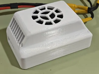
This is the final result, the whole unit weighs about 200g, I hope it can be helpful to others :)

The enclosure consists of two parts: top and bottom.
You may need the following additional parts:
- 4 x 16mm M3 hex screws
- 8 x 6mm M3 countersunk screws
- 4 x M3*5*4 injection molded nuts
- 4080 3mm aluminum alloy heatsink
- FPC antenna (5DB 50*14mm) with 13cm IPEX 4th gen connector (plugs into AUX 1)
- FPC antenna (7DB 65*15mm) with 13cm IPEX 4th gen connector (plugs into MAIN 2)
You can click the green text to jump to the purchase link.
Assembly Guide:
⚠Before starting assembly, please ensure that any stringing or overhang imperfections on the printed parts have been trimmed with a utility knife or smoothed with sandpaper.
① Use a soldering iron to insert the knurled injection molded nuts into the four holes of the printed part.

Please ensure the nuts are embedded deep enough (as shown).

② Completely cover the exposed parts of the two antennas with acetate tape (or any other insulating tape):

③ Adhere the two antennas into their respective grooves of corresponding sizes.
It is recommended to first peel off the release liner from one side of the antenna, adhere that side, then use tweezers to help peel off the release liner from the other side:

Note: The top shell has reserved routing grooves for the 5DB antenna. Bend the coaxial cable along its path to embed it in the groove, then tape down the indicated positions (especially the topmost tape).

The 7DB antenna is installed the same way:

Here, the coaxial cable needs to be bent as shown and secured with tape:

④ Push the NX core carrier board module into the top shell, then connect the antennas to their bases (be careful during this step to avoid the PCB edge scratching the coaxial cable; if your printed part has too many imperfections, the core board and enclosure might not fit perfectly in this step).

Route the cables as shown, connect the WiFi antennas, and secure the coaxial cables:

⑤ Assemble the bottom shell and heatsink
Use 8 x 6mm M3 countersunk screws, tightening them diagonally in sequence to secure the heatsink to the bottom shell.

Please ensure not to use screws that are too long; correctly sized screws should not protrude excessively beyond the height of the heatsink on the back:

⑥ Secure the bottom shell and top shell:
Before this, it is recommended to apply thermal paste or thermal pads to the surfaces of the power delivery alloy inductors, SSD, and network card. The thickness will vary depending on the situation (the network card area is often particularly thin).

Then use M4 screws to secure the bottom shell (be careful not to overtighten these four screws, as it might pull the embedded nuts out beyond the plastic surface; it's recommended to tighten them by hand with a screwdriver bit until appropriately snug).

Assembly is now complete.
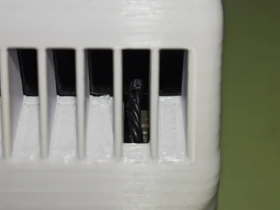
The top shell has 3 reserved holes, allowing you to use a slender object to press the buttons on the board:

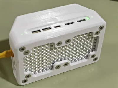
Additionally, openings are provided for the light indicators, allowing observation of the carrier board status:

Here are detailed illustrations:


The enclosure has special optimizations for peripheral interfaces, allowing full connectivity without any pressure (the FPC ribbon cable for the camera module requires removing the bottom plate for installation):


Comment & Rating (0)