PanelMaker


Print Profile(2)


Description
This tool will design files for rack panels suitable for use in 10-inch mini racks such as the GeeekPi server rack series. It is parameter driven and the user can create a panel with up to 10 devices mounted to the panel.
The predefined devices are:
- Space — create a space of specified width (default 0). This is the default device for each position.
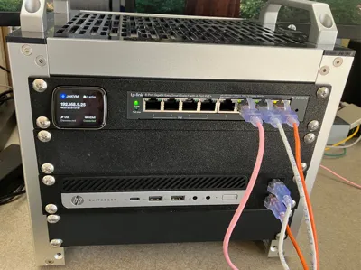
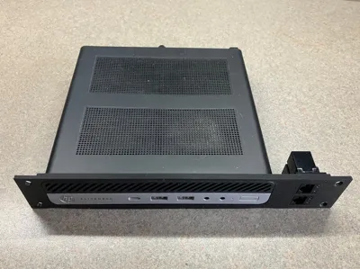
- SG108PE — This fits a TP-Link SG108PE layer 2 POE switch. It might also fit other devices in that product line. It has a rectangular opening in the panel and has a shelf behind the panel for supporting the switch. There are also mounting holes through the shelf for the device. I used M4 bolts and nuts, but other sizes might work.
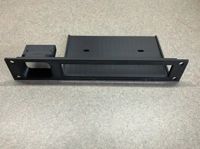
- JetKVM — This will create a place to mount a JetKVM. There are two holes for mounting. Use M2-0.4x8 round or button head metric bolts.
- HPEliteDeskG2 and HPEliteDeskG5 — These will hold an HP EliteDesk 800/700 Series Mini PC of the given generation. These two only differ by the radius of the corners. There is an opening to match the front of the device and a shelf below with Vesa mount holes. Use M4-0.7x8 flat head bolts. If you want to try other HP EliteDesk PCs, you may want to experiment with the radius parameter (see below).
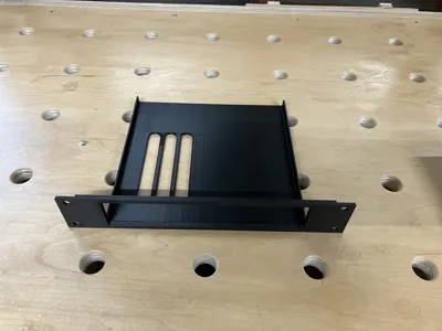
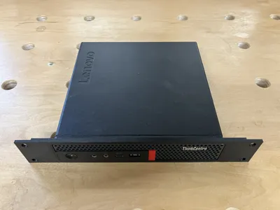
- LenovoM90 – This will hold a Lenovo M90q or M920q and likely others in the family, maybe even P330s and P340s. There are vent slots in the bottom of the shelf positioned to allow airflow through to any NVMe SSDs. Because these slots are being printed vertically along with the shelf, they are made with arched tops to try to get by without supports. YMMV.
- Switch — The generic network switch shape. It is a rectangular hole in the panel with a shelf below. All dimensions default to 0 so they must all be supplied via parameters (see below). The SG108PE and HPEliteDesk are just special cases of this device.
- Keystone — This will fit one keystone jack. The jack is mounted vertically.
- Keypair — There is just enough room in 1U to mount two keystone jacks, but they are rotated 90 degrees to fit.
- Square — This will generate a square hole. Use parameters for sizes. To produce a rectangle, give separate height and width. A radius can be specified to round the corners. To create an oval, set the radius to half the width or height.
- Polygon — This creates a polygonal hole, but defaults to an infinite number of sides, i.e, a circle. Set sides to a smaller number to get a real polygon. You may specify a radius for corner rounding. The polygon will be oriented such that the top face is parallel to the panel edge. Use rotation to change this. Note that the size specified will be the size of the circumscribing circle. This means to get a 20mm square you must specify a size of 20 * √2 or approximately 28.28. Adjusting for other polygons is left as a trigonometric exercise for the user.
The shapes are chosen using the OpenSCAD Customizer. They are "Device_1" through "Device_10".
For each device the user can, and in some cases, must supply definitions for height, width, etc. This is done via a simple text string supplied via the OpenSCAD Customizer as values "Parameters_for_Device_1" through "Parameters_for_Device_10". The text string is broken down on commas into "name=value" pairs. The values are all numeric. The parameters supported at this time are (all lower case):
- width — Abbreviation:"w". This is used on all devices to set the width. For most devices it defines the opening in the panel into which it fits.
- height — Abbreviation:"h". This is used on all devices to set the height. For most devices it defines the opening in the panel into which it fits.
- size — The value for size can be defined and it will be used for both the height and width, unless explicitly overridden.
- sides — The number of sides in a polygon.
- pad — This defines a little extra room to be added to each side of the opening. If the device has a wall defined for it (see below), the padding overlaps the wall's thickness so the real space consumed is the greater of the two values.
- rotation — Abbreviation: "rotate". This is the rotation in degrees applied to the whole device. Note that any extra (or less) space needed to fit the rotated device is not calculated in the alignment. Use pad to manually adjust for this. A rotate=180 might be useful to apply to a Keystone to orient an Ethernet jack's push tab conveniently.
- depth — Abbreviation: "d". If the device needs a shelf or ledge to rest upon, this defines the depth of that shelf. It is measured from the frontside surface of the panel.
- thickness — Abbreviation: "t". This sets the thickness of the shelf or ledge. This shelf will be aligned with the bottom of the opening in the panel.
- shelfwidth — Abbreviation: "sw". This sets the shelf's width if it needs to be different from the width. A value of zero will cause it to default to width. Reducing the width might be useful if there are ventilation holes in the bottom of a device near the edge. A shelfwidth that is less than width will suppress the walls.
- radius — Abbreviation: "r". This is used to effect rounded corners for a panel opening. It can be used with the Switch shape and its derivative SG108PE. It can also be used with Square or Polygon to give them rounded corners.
- wallheight — Abbreviation:"wh". If the device has a shelf for support, this sets the height of it. It is likely best to be a small lip and not the full height of the device because they often have ventilation holes on the sides. However, adding to the wall's height or thickness will help strengthen the shelf.
- wallthick — Abbreviation:"wt". If the device has a shelf for support, this sets the thickness of it. It is also used, for instance, for the thickness of the shroud around the JetKVM.
- shelfoffset — Abbreviation: "so". For some devices, such as the HPEliteDesk, the shelf does not line up with the bottom of the opening. In this case the shelf needs to be offset down (negatively) while the opening is offset up (positively).
- openingoffset — Abbreviation:"oo". This is to offset the opening, as mentioned above.
- vent_left, vent_right, vent_front, vent_back – These only affect the LenovoM90 devices and define the location of the venting.
- vent_arches, vent_column – This is the number of arches and the column width between arches, also only for LenovoM90.
Using all the parameters above it should be possible to recreate the HPEliteDeskG5 using the Switch device with parameters set to: w=178.5,h=35,d=165,r=7,t=2.5,wh=20,wt=2,oo=1.776,so=-2.224. However, it won't make the holes for you. Currently there is no way to specify holes via parameters.
There are a few overall settings:
- Units — currently all measurements are in mm. The parametric interface to OpenSCAD does not support anything fancy like recalculating other displayed values when the units change.
- Panel Width — 10-inch and 19-inch panels are supported; however, 19-inch is untested.
- Panel Thickness — The whole panel is at least this thickness.
- Panel Stiffener — This is extra thickness to the central part of the panel between the mounting rails. It is assumed plastic needs to be thicker for some heavy objects, but it should only be thicker between the mounting ears.
- Mounting Width — The default is the value shown on the documentation found on Wikipedia. This can be adjusted if necessary.
- Mounting Hole — This determines what bolt sizes to use for mounting. The default fits the common rack sizes of M6 (Metric) and 10-32 (US). My GeeekPi rack came with 10-32.
- Alignment — The locations of devices are assigned with Device 1 in the leftmost position, Device 2 next, etc., but the alignment choices are:
- Left: As close as possible against the left side.
- Right: As close as possible against the right side.
- Centered: As close as possible with the extra space split between left and right.
- Justified: Split the extra space as evenly as possible to have Device 1 on the left edge and Device n on the right side.
- Minimal Spacing — If the devices should be clustered together (not justified), but they are too close, the minimal spacing can be set.
The file PanelMaker.scad is what makes these panels on the Parametric Model Maker. It also should work with OpenSCAD running on your own computer. It will not run on the stock OpenSCAD available on Fedora. Your best bet on almost all platforms is to download one of the Development Snapshots from here: https://openscad.org/downloads.html#snapshots. I used OpenSCAD-2025.03.21 while developing this.
If you are going to regularly work offline or want to extend this project to include other devices, you should download the accompanying ZIP file PanelMaker.zip. It includes the documentation, several SCAD files and a Makefile to build the PanelMaker.scad and ZIP file from the constituent parts. This is needed because though OpenSCAD supports local include files, the MakerWorld PMM does not. They must be combined into one huge mess before upload. The Makefile assumes python3 is available and the OS is Unix (MacOS) or Linux (Fedora). It has not been tested on Windows in any environment like Cygwin or Windows Subsystem for Linux.
Comment & Rating (20)