
Moza SR-P Lite Pedals Load Cell Mod
Print Profile(1)

Description
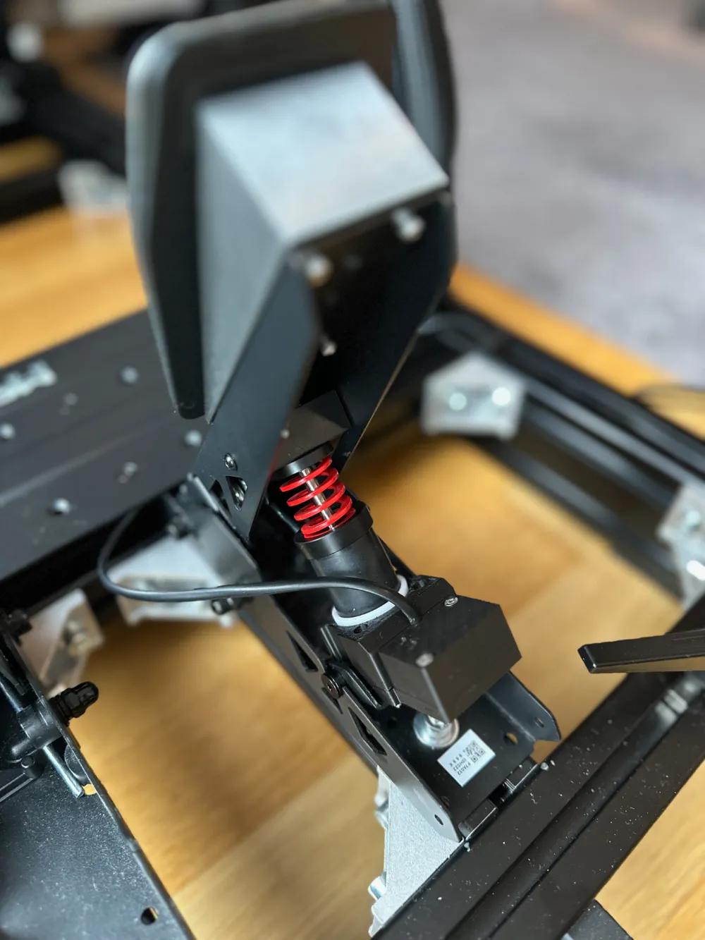
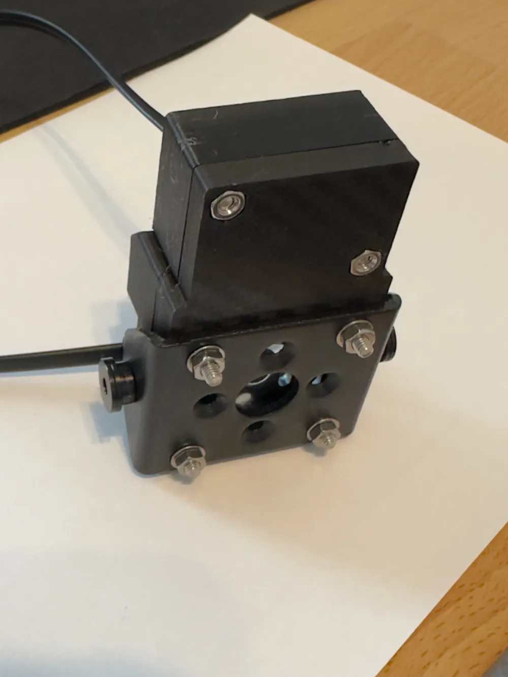
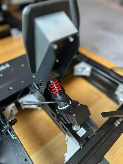
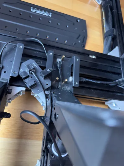
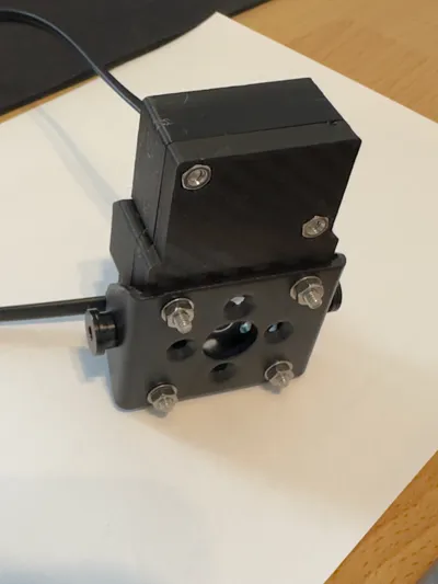
I have created a load cell mod for the Moza SR-P Lite pedals.
📄Function

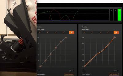
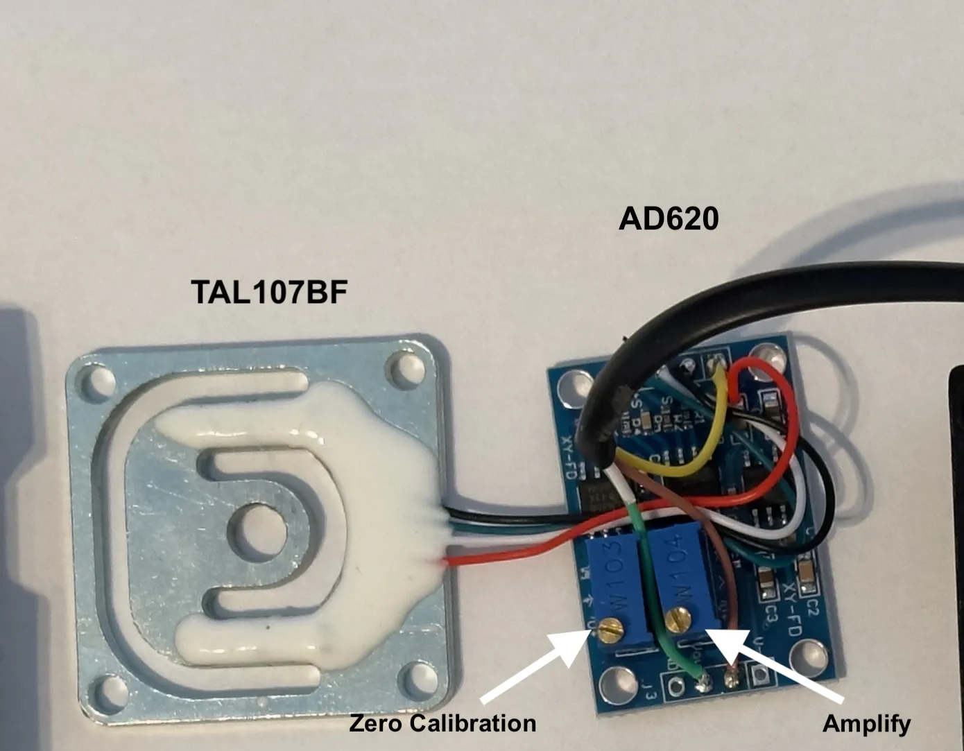
The original hall sensor manages a 3.3V signal. At rest, the brake pedal exhibits approximately 0.4V. This necessitates adjustment using the AD620 and the zero-calibration screw. A multimeter or the original Moza tool is best suited for this. The gain screw allows adjustment of the pedal travel required to reach 100% or 3.3V.
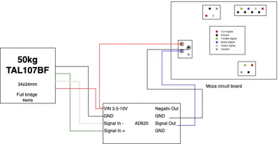
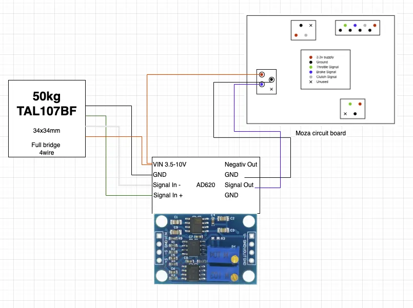
Measurement is conducted between GND and Signal Out on the AD620.
🪛Build
3D print the files. Structural integrity is paramount. I used PLA; PETG or ABS are likely superior.
Assemble and solder the components. Test the load cell sensor before securing the enclosure.
🔥Soldering
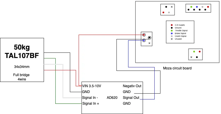
Connect the four wires to the AD620. Keep the load cell sensor wires to a maximum of 3-4cm in length.
The 3.3V positive lead from the Moza board must connect to both the load cell sensor and the AD620—both require power.
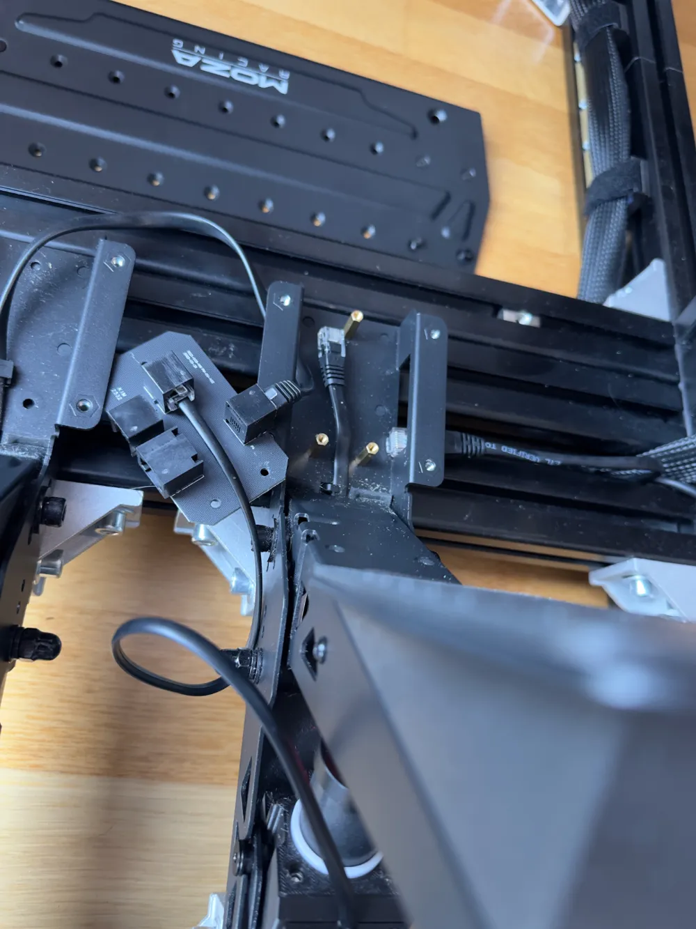
RJ11 connectors exhibit variability in pin and color configurations. Use the Moza diagram to verify and assign pinouts correctly. One pin remains unused.
🔧 BOM
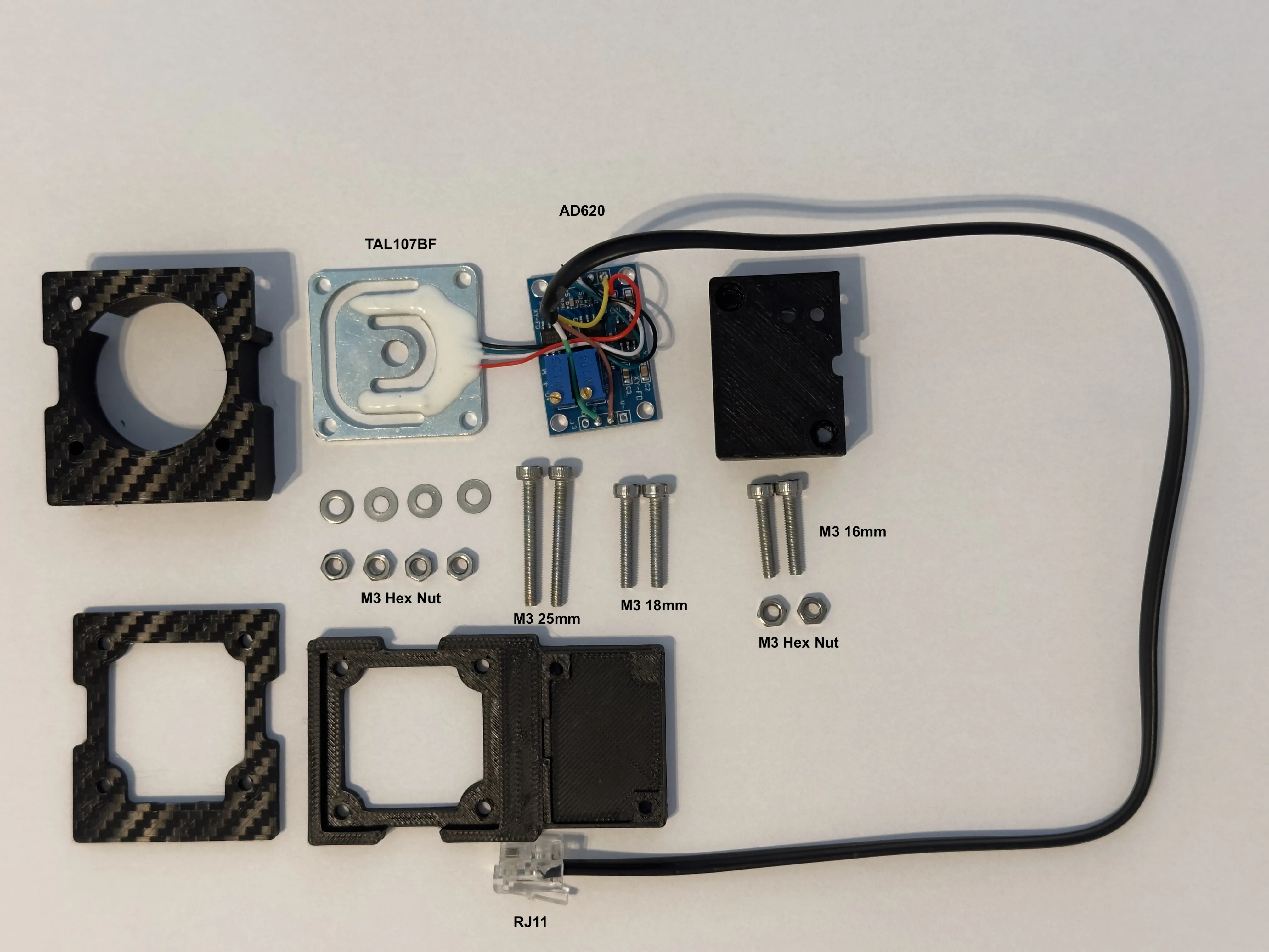
1x AD620
1x TAL107BF Full bridge 50KG Load Cell
1x RJ11 cable 20cm
2x 25mm M3 screws
2x 18mm M3 screws
2x 16mm M3 screws
6x M3 Hex Nuts
Boost Me (for free)
If you like it. It's free :)
License

You shall not share, sub-license, sell, rent, host, transfer, or distribute in any way the digital or 3D printed versions of this object, nor any other derivative work of this object in its digital or physical format (including - but not limited to - remixes of this object, and hosting on other digital platforms). The objects may not be used without permission in any way whatsoever in which you charge money, or collect fees.


Comment & Rating (92)