Search models, users, collections, and posts
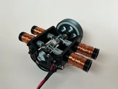
Solenoid Mini Engine | Four-Cylinder Electric
IP Report


Print Profile(1)

AllParts 0.2mm layer, 3 walls, 15% infill
Designer
3.4 h
4 plates
Open in Bambu Studio
Boost
70
85
1
1
35
10
Released
Description
It runs at a good speed at 7V 2A.
Parts Needed:
- 5mm steel rod (≥110mm long) https://a.co/d/i9PcLPT
- Copper wire 0.5mm (~80g needed for each coil) https://a.co/d/8sGAtHW
- (2) 16x5x5mm bearings https://a.co/d/6BE9lIB
- (28) Cylindrical magnets (28x 10x3mm https://a.co/d/1pj4dlN)
- (2) Limit Switches https://a.co/d/0hFRVpu
- M3 Bolts and Nuts
- (1) capacitor at least 25v and high capacitance https://a.co/d/7JtPDyL
- (2) Diodes at least 25v 5A rating https://a.co/d/hw464Bk
- Cut the 110mm steel rod into 2 30mm, 2 15mm, and 1 20mm sections then glue together with the ShaftConnectors to make the shaft.
- Push 7 magnets into each piston (don't fill the whole piston with magnets there should be extra room)
- Attach the PistonConnectHooks to the pistons with M3x10mm Bolts.
- Attach the other side of the hooks to the shaft.
- Push bearings into the front+back sides.
- Glue the coil caps onto the CoilBody parts.
- Wrap wire around the coils ~80g each coil.
- Glue the CoilBodies into the left and right sides.
- Put the shaft through the bearings, the pistons in the CoilBodies, and put the sides together with M3 bolts.
- Put the bottom on with M3 bolts.
- Wrap something heavy like copper wire around the flywheel then glue the cover on. (may work without wire inside or use different flywheel)
- Put the Flywheel and Ignitionwheel on the shaft (don't glue the Ignitionwheel down yet) may need to add spacers.
- Put the switches on the side with holes attatch with M3 bolts.
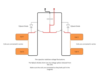
- Wire the switches, capcitors, diodes and coils together. (see circuit diagram)
- Make sure the ignitionwheel is turned so it activates the coils when they are ready to be pulled in.
License
This user content is licensed under a
Creative Commons Attribution-Noncommercial-Share Alike
Comment & Rating (1)