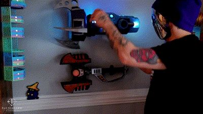
Ratchet and Clank Plasma Storm Replica


Print Profile(1)

Bill of Materials


Description
Summary
This is an exact 3D model of the Plasma Storm weapon from Ratchet & Clank: Going Commando (PS2). I modified the model to be fully 3D printable, hollowing out certain sections to allow for the integration of LED lights and a motor. The design stays true to the original game asset while making it practical for printing and assembly. Perfect for display or cosplay!
If you like my work, why not buy me a cup of coffee! paypal.me/FletchFormStudios
Parts used:
Most of the parts were from the Bambu Maker Supply Store. https://us.store.bambulab.com/collections/makers-supply
The only parts not supplied by Bambu were M2, M3, washers, a 3 x40mm metal dowel, and heat-set inserts that I already had on hand.
LEDS:
4x 4 White 3030 LED Board with SH1.0 Connector 5V - KB001
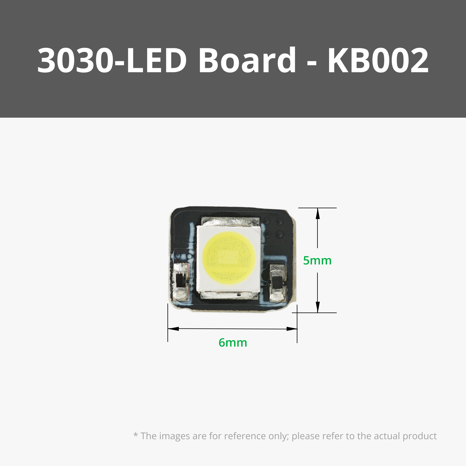
4x 1 White 3030 LED Board with SH1.0 Connector 5V - KB002
1x COB LED Strip Light 300x1mm - KA009
Electronic parts:
1x N20 Reduction Gear Motor 150rpm LA002
2x Power Distribution Board - 4 Channels - IA005
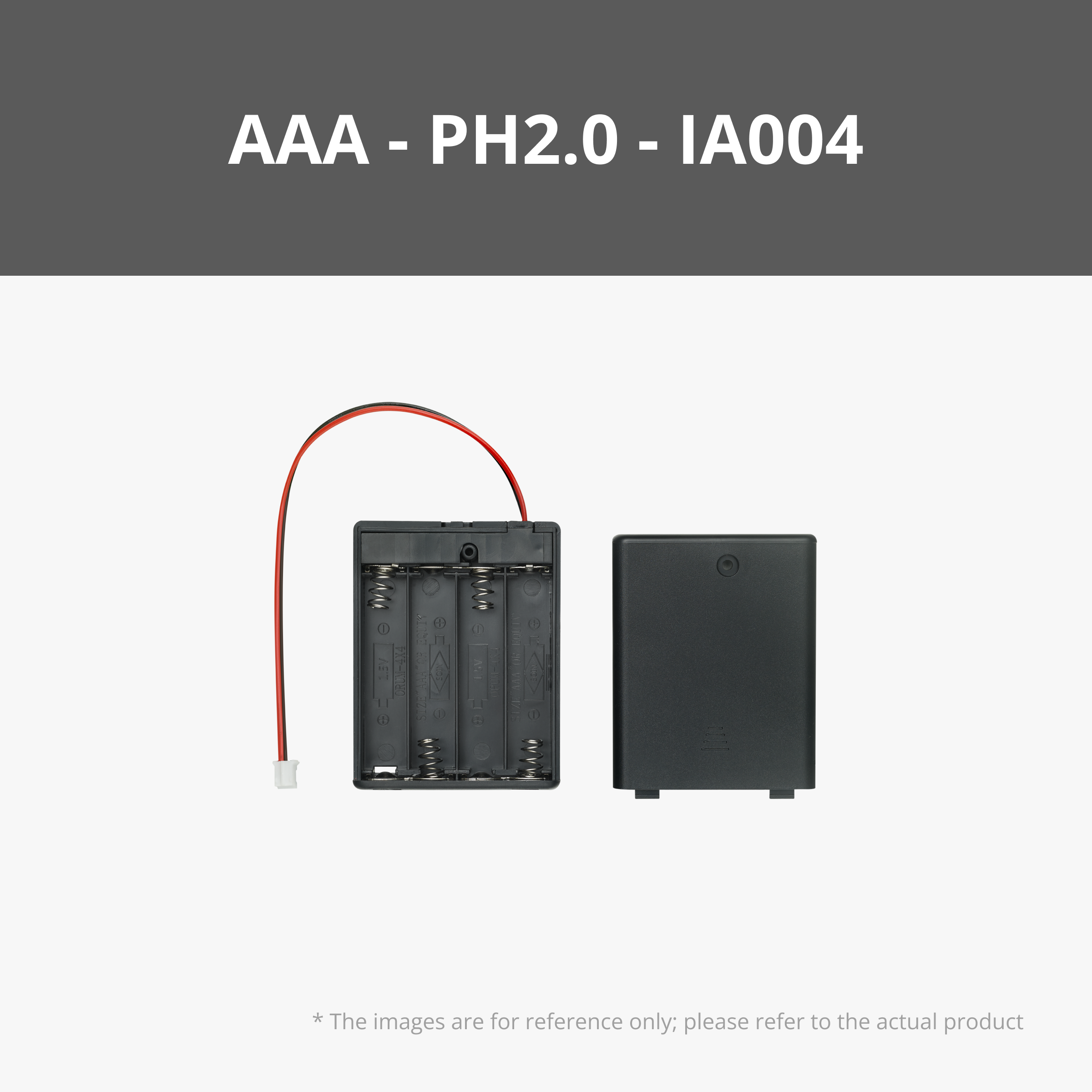
1x AAA Battery Case with PH2.0 Connector - IA004
1x Self-Locking Button Switch (2PCS) - IA006
1x Rechargeable Power Kit - ZC003
Wires and Connectors:
x8 100mm Wire with SH1.0 - IC004 (with extras just in case)
x8 200mm Wire With SH1.0 - IC007 (with extras just in case)
x9 Jumper Cable with SH1.0 Connector - IC006
x2 100mm Wire with PH2.0 - IC008
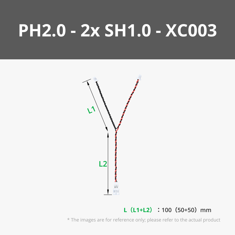
x1 100mm Y Type PH2.0 to Dual SH1.0 Conversion Wire - XC003
x1 150mm ZH1.5 to SH1.0 Conversion Wire - XC007
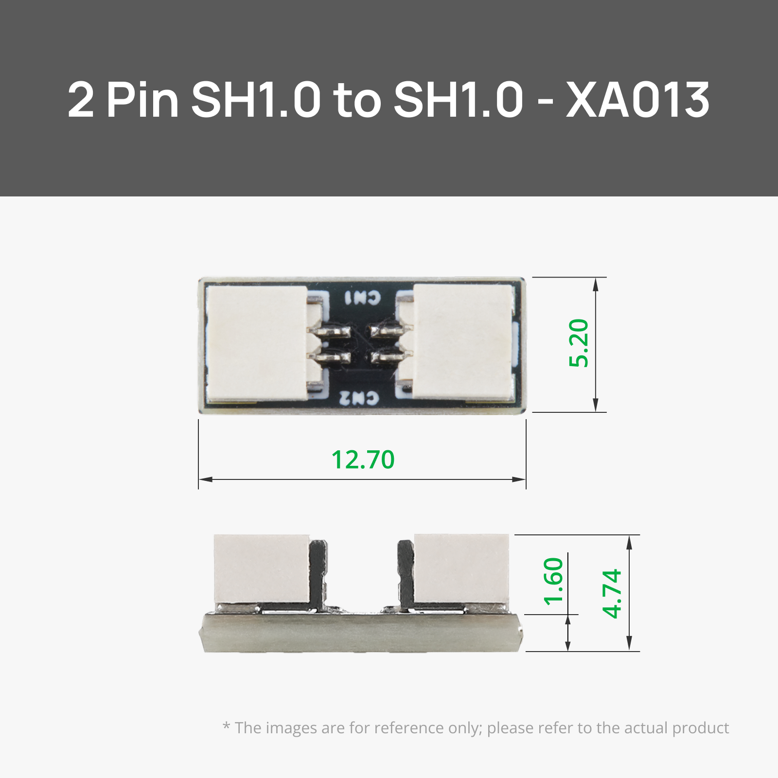
x6 SH1.0 to SH1.0 Connector Adapter Board - XA013
Bolts/Washers/Pin/Magnets/Heat-Set Inserts/Spring/Bearing
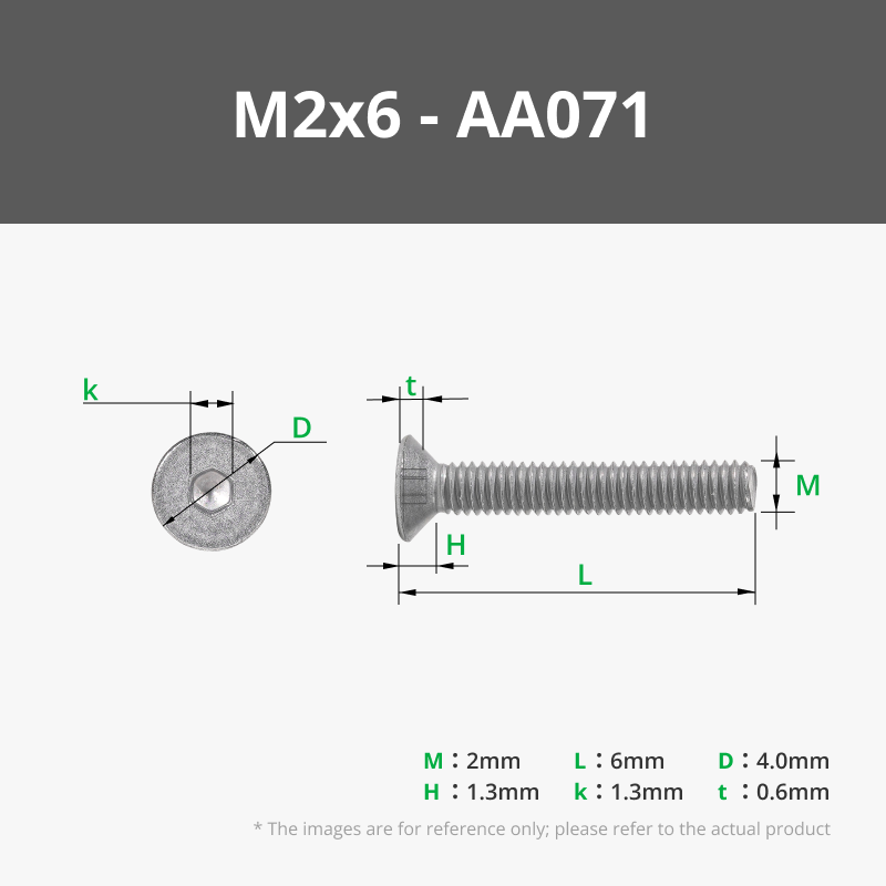
1x M2x6 or M3x bolt for motor coupling
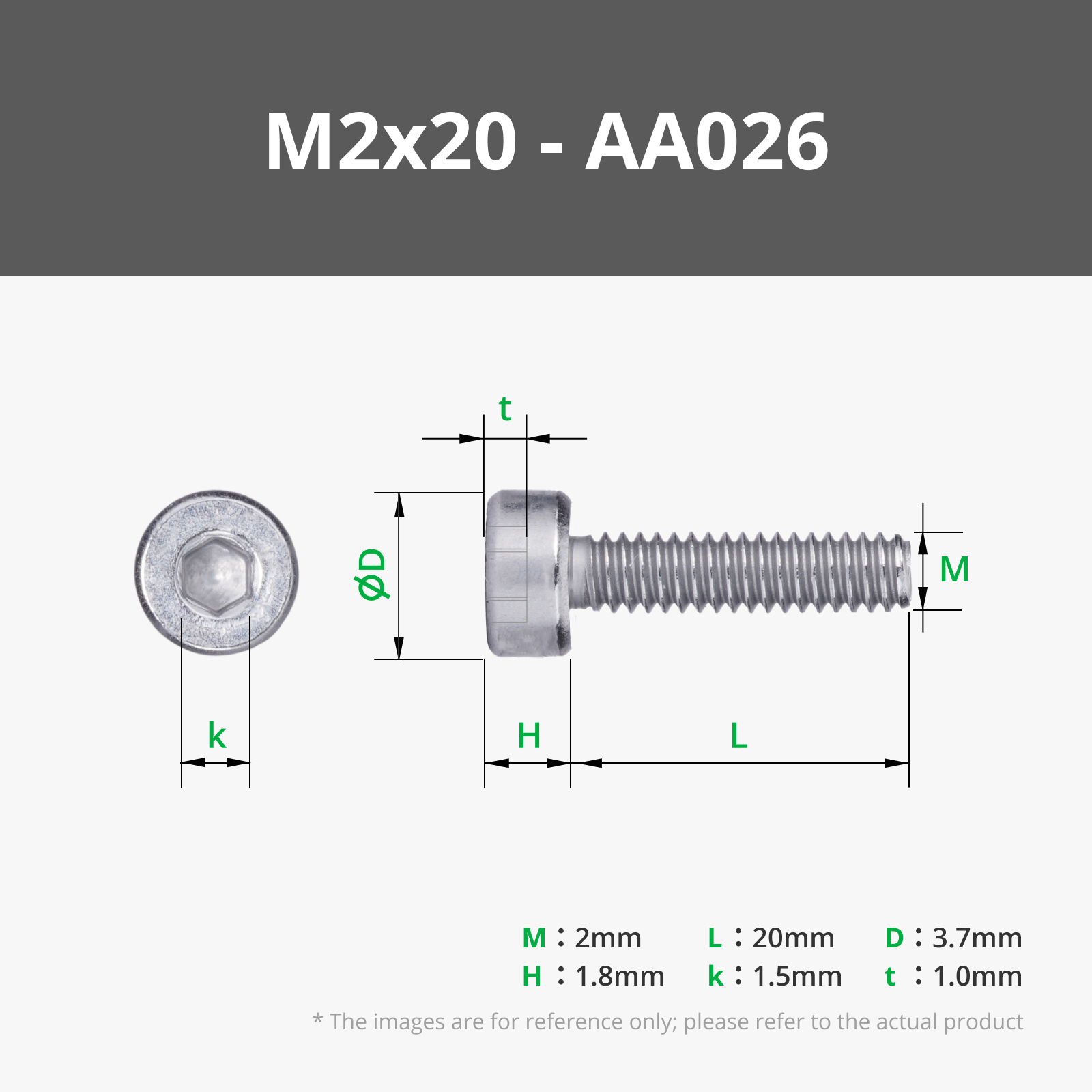
x2 M2x20mm Bolts
x2 M2x10mm Bolts
x3 M3x10mm Bolts
x2 M3x16mm Bolts
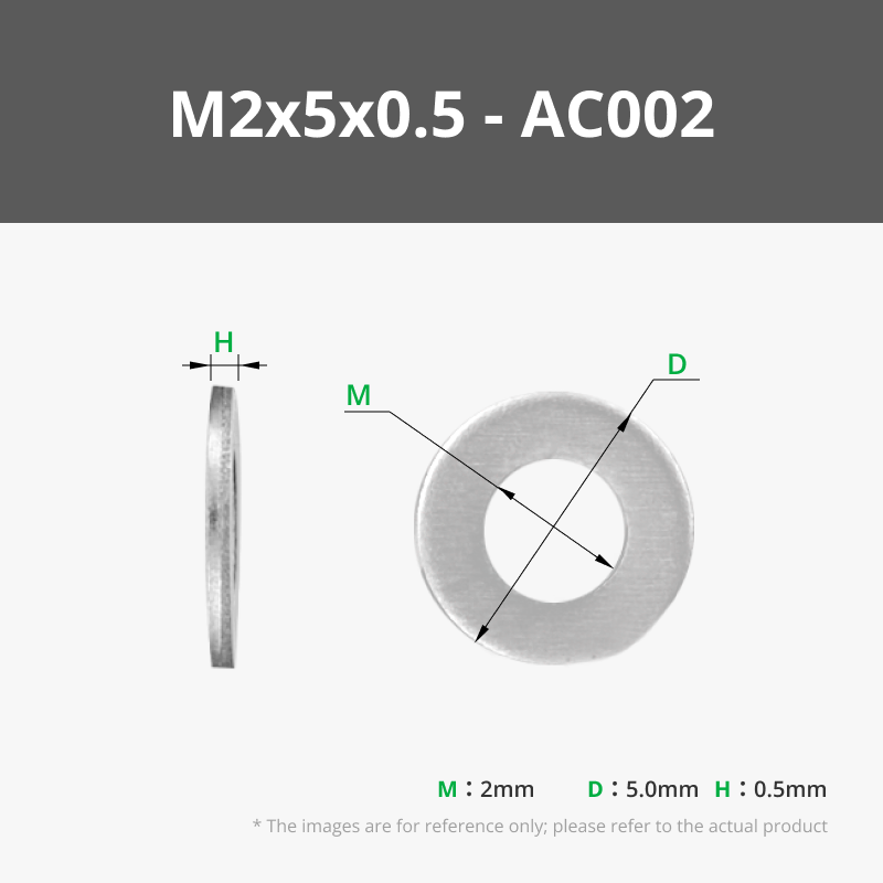
x4 M2 Washers
x5 M3 Washers
x12 10x3mm magnets
x4 M2x4 Heat-set inserts
x5 M3x5.7 Heat-set inserts
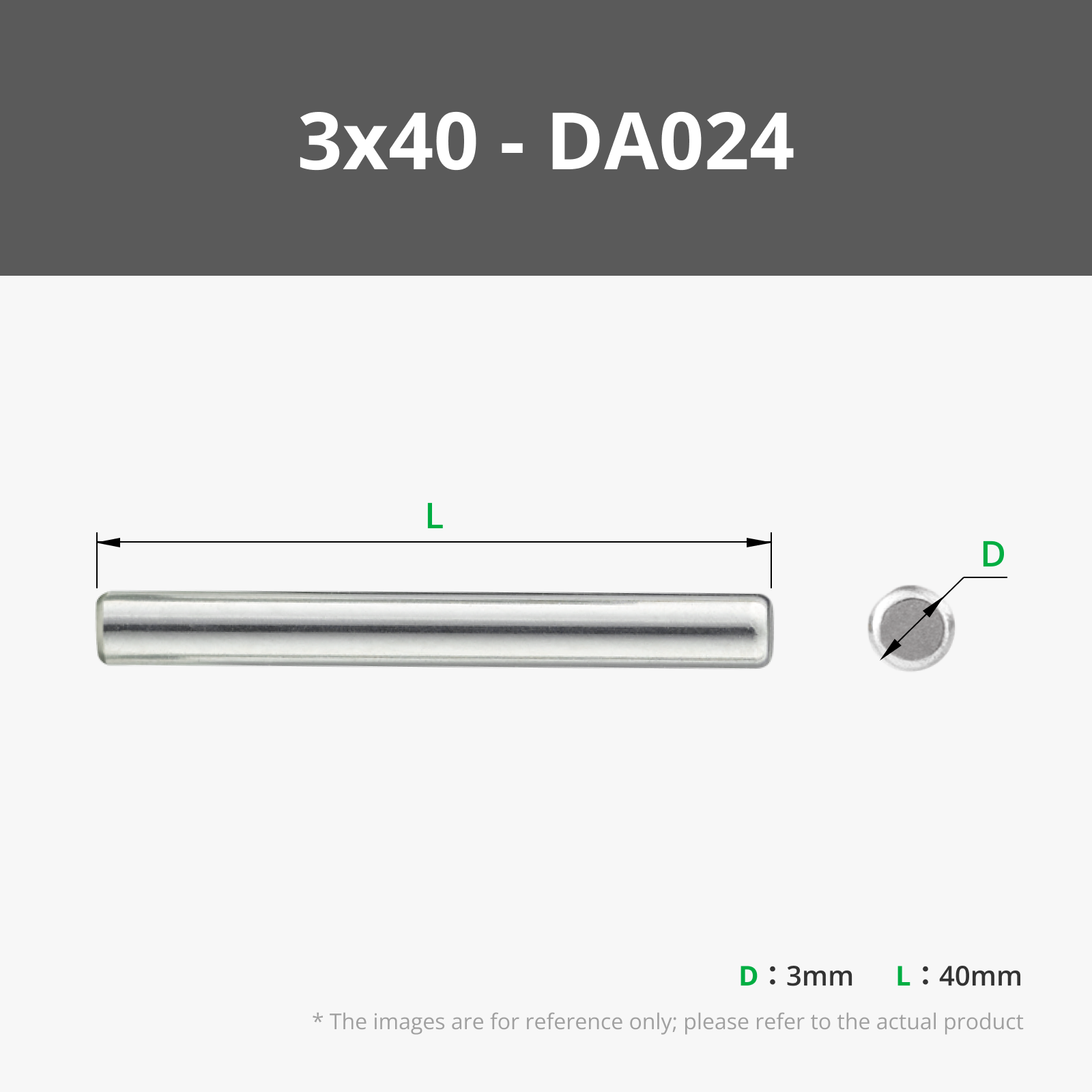
x1 3x40mm Dowel Pin
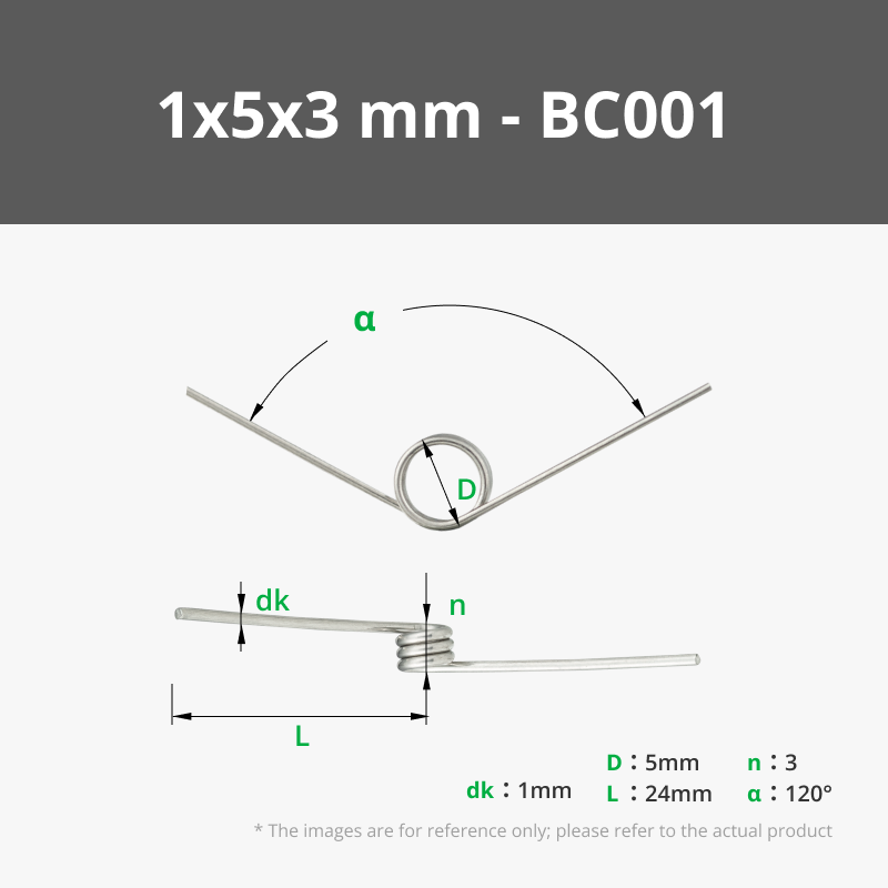
x1 1x5x3 mm 120 Degree Torsion Spring - BC001 (ends are trimmed to fit)
x1 Plastic Deep Groove Ball Bearing 6204 - EA002
Assembly:
I am not going to lie, this is going to be a slight pain and require a lot of trial and error.
I dry-fitted all the electronics first. Then I took it all apart to paint, and reassembled permanently afterwards.
Keep the body parts separate for now until all electronics are in place. Then once correct, glue the printed dowels into the bodies, and glue the bodies together.
- Insert the heat-set inserts into their respective holes in the main body for hardware component. The smaller heat set inserts go into the smaller holes, and the bigger inserts into the bigger holes.
- Take the N20 motor and attach it to the shaft guard part using the tiny screws provided with the motor. Attach the coupling module to the shaft of the motor using an M2x6 or M3x6 bolt and tighten.
- Attach the star shaft part to the motor coupling. (I glued it with super glue since I don't ever plan on replacing it.) Attach the muzzle connector to the star shaft using glue.
- Slide the motor assembly in the the opening of where the muzzle will go.
- Insert the bearing into the respective hole over the motor shaft.
- Take the motor mount part put it over the N20 motor body and bolt it down using the respective M bolts/washers.
- Take the self-locking button switch and bolt it to the opposite wall of the motor using the respective M bolts/washers. Making sure to keep the wire connection opening facing away from the the wall.
- Attach the AAA battery case holder part by bolting it down using the respective M bolts/washers. Then insert the actual AAA battery case into it making sure the wire is facing downwards.
- Take the trigger part and put the torsion spring into the circular opening with one end following the grove up the trigger. The other end should be facing right. Insert the trigger and spring into the opening for the trigger. This will require some finessing, I used a thin flat tool to help me get the spring in the groove of the body. I did have to trim each end of the spring about 2-3mm with a wire cutter. Make sure the circular part of the spring aligns with the hole on the body.
- Take the 3x40mm Dowel pin and gently hammer it into the hole for it for the trigger assembly. Again, this will require some finessing to get the spring, and trigger to align. Once in place, you will have to move the trigger back and forth and adjust the position to get it to smoothly hit the switch and retract.
- Take each LED and attach the appropriate length of wire FIRST. You might have to snip the little white tabs of the wire connections ends to get them to fit perfectly through the holes. I found feeding the wires through the holes first THEN adding the LEDS works best. Put a dab of glue on the back of each LED (except for the tube ones) and place them into each LED port with the LED connectors facing the holes so the wires can pass through.
The side grates use the 4 white LEDS with 100mm SH1.0 wires
The side bubbles use 1 white LEDs with 200mm SH1.0 wires, chained together using the 150mm ZH1.5 to SH1.0 Conversion Wire which itself was chained using a 100mm Wire with PH2.0 - IC008
The side tubes use 1 white LEDS with 2 200mm SH1.0 wires chained together using SH1.0 to SH1.0 Connector Adapter Board - XA013, I made these LED face towards the back and used hot glue to hold them into place.
The back LED uses a 4 white LED with 2 200mm SH1.0 wires chained together using SH1.0 to SH1.0 Connector Adapter Board - XA013, make sure to attach the LED and thread the wire through the opening shaft FIRST before you attach the back component to the body permanently. - Feed all the wires through their respective holes and towards the hardware body.
- Attach the AAA battery pack wire to the power in port of one of the Power Distribution Boards.
The ports will be be filled with the following wires:
Power Distribution Board 1:
In: AAA battery pack wire
CH1 100mm SH1.0 wire to N20 motor
CH2 100mm SH1.0 Wire to right pane 4 white LED
CH3 100mm SH1.0 Wire to left pane 4 white LED
CH4 empty
Out 100mm PH2.0 wire
SW0 Jumper cable
SW1 Self-locking button
SW2 Jumper cable
SW3 Jumper cable
SW4 Jumper cable
Power Distribution Board 2:
In: 100mm PH2.0 wire from power distribution board 1 out
CH1 100mm SH1.0 wire to (sh1 to sh1 connector adapter board) to 200mm SH1.0 wire, to top 4 white LED
CH2 100mm SH1.0 wire to (sh1 to sh1 connector adapter board) to 200mm SH1.0 wire, R tube 1 white LED
CH3 100mm SH1.0 wire to (sh1 to sh1 connector adapter board) to 200mm SH1.0 wire, L tube 1 white LED
CH4 200mm SH1.0 wire to (sh1 to sh1 connector adapter board) to 200mm SH1.0 wire, back 4 white LED
Out 100mm PH2.0 wire to 150mm ZH1.5 to SH1.0 Conversion Wire, which connects 2 (sh1 to sh1 connector adapter boards)to 2 100mm SH1.0 wires, to 1 white LED for the side bubbles.
SW0 Jumper cable
SW1 Jumper cable
SW2 Jumper cable
SW3 Jumper cable
SW4 Jumper cable
- Take the distribution board standoff and put them between the 2 distribution board stacked on top of each other. Put the 2 M2x20mm bolts and washers and put them through the distribution board holes and attach them to the heat-set inserts in the bottom right of the hardware compartment.
- Put in 4 AAA batteries into the pack, and test that all the LEDs work when you turn the battery pack on. Test the motor by pressing the trigger.
- Attach the panes to all the respective LED components on the body
- Glue the side grates and back LED component into place.
- For the side bubbles, I printed a thin sheet of PLA (.2mm) and used a heat gun to melt it into a bubble shape, cut the access off, and then glued it over the LEDs.
- Attach the side tubes, side bolts, and handles using glue.
- Take the muzzle opening and place the COB LED Strip Light 300x1mm - KA009 around the circle indent using glue, take the little circuit board attached to this and glue it to spot for it at one end of the circle.
- Attach the Rechargeable Power Kit - ZC003 circuit board to the slot with the 2 openings making sure to align the USB C and button switch with each respective hole.
- Take the power button part and press it through the circular opening on the outside of the muzzle until you feel it get press over the self locking switch of the power kit.
- Connect the provided rechargeable battery and glue it to the square space next to the circuit board.
- Connected the 150mm ZH1.5 to SH1.0 Conversion Wire - XC007 from the rechargeable circuit board to the COB LED strip.
- Test that the LEDs are working.
- Glue the 8 pane standoffs right below the grove inside the muzzle, this will hole the pane's in place.
- Put a dab of glue on top of each stand off and take the pane halves and try to slide them into the groove while pressing them down on the standoffs.
- Attach each muzzle spike using glue, each muzzle spike has slightly different dimensions (for some reason they did in the video game and I didn't bother to change them due to laziness) so just test fit each one in each hole to figure out where each one fits, then glue them down.
- Glue the muzzle connector to the back of the muzzle opening.
- Attach each 10x3mm magnet to the hardware body opening and the body cut out part, making sure to check the magnet polarities. Connect the body cut out panel to the body.
- You should be done now! Enjoy your Ratchet and Clank gun brought to life!!!
Side Notes:
For the LED panes, I used resin printing AND FDM printing to achieve the look. I resin printed each pane with the resin printing part, wet sanded them smooth and shiny, then printed a blue thin .2mm FDM layer and glued them over the resin printed panes. This helped me get the light diffusion I was looking for.
The side tubes really only can be printed in clear resin I learned. Be sure to split the tubes in half in whatever slicer you use to actually be able to fit them onto the part, then glue them back together once they are attached to the sides of the gun, ask me how I know this now lol.
I designed this for myself since this game means a lot to me and it was always a childhood dream of having this weapon in real life, so if there's mistakes (which there absolutely is) I am sorry, feel free to modify this model for yourself! This is why I didn't include super in-detail assembly instructions with pictures since it was more for myself than anything. Also, if you have an questions or want clarifications on anything, please don't hesitate to each out!
If you like my work, why not buy me a cup of coffee! :) buymeacoffee.com/FletchFormStudios
Boost Me (for free)
Love this design? Show your support by giving it a boost! Your encouragement inspires me to create more unique and fun designs for the community. Share your makes and spread the creativity!
Comment & Rating (3)