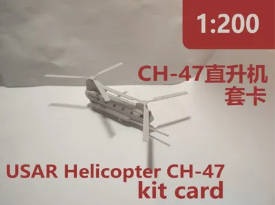
1:200 scale CH-47 helicopter assembly kit (CH-47)


Print Profile(1)

Description
Boost Me (for free)
If you appreciate this model, your support would be greatly valued
Requisite tools for assembly: a keen-edged blade, adhesive, and a sanding board
Beyond the main structural components, the principal challenging assembly stages are as follows
1. Disaggregate each component, store them within diminutive receptacles, and subtly refine their surfaces

2. Assemble them meticulously as depicted in the accompanying illustration, lightly abrade both flanks, to mitigate any areas previously overlooked in the polishing process

3. Prepare the constituent parts of the engine. Either the two contiguous components on the extreme left or the two on the extreme right constitute a complete engine assembly, ensuring no intercrossing

Orient one segment perpendicularly, maintain its immobility, dispense a small quantity of adhesive onto its uppermost surface, and then secure the complementary segment into its precise alignment

4. Affix the propulsion unit to the airframe(Prior to permanent adhesion, it is prudent to pre-test the fit of the apertures)


5. Disassemble the diminutive wheels; ensure one hand firmly secures the component while the other executes the incision, lest the minute components inadvertently detach and escape

Beyond merely removing the foundational vestiges from the wheel surfaces, furthermore, position the wheels upright, and meticulously clear any residual material perceptible from the vantage point illustrated below

6. At this juncture, the wheels may be installed; however, the model may exhibit varying manufacturing tolerances, thus one may judiciously insert the tip of a precision blade into the bore and rotate it to subtly enlarge the aperture

Following a successful preliminary fitting, then carefully disengage the component, apply a modest quantity of adhesive, and then firmly reinstate it. This identical methodology should be applied to the remaining three perforations

7. Opaque the cockpit canopy with a black coating, subsequently affixing it to the principal structure. Thereafter, integrate the propellers and fuel conduits; non-adhesion is recommended for these elements. The ultimate aesthetic is presented in the accompanying illustration
(The propellers possess no inherent directional orientation and are of uniform dimensions)

License
You shall not share, sub-license, sell, rent, host, transfer, or distribute in any way the digital or 3D printed versions of this object, nor any other derivative work of this object in its digital or physical format (including - but not limited to - remixes of this object, and hosting on other digital platforms). The objects may not be used without permission in any way whatsoever in which you charge money, or collect fees.
Comment & Rating (5)