


Print Profile(1)

Description
Overview
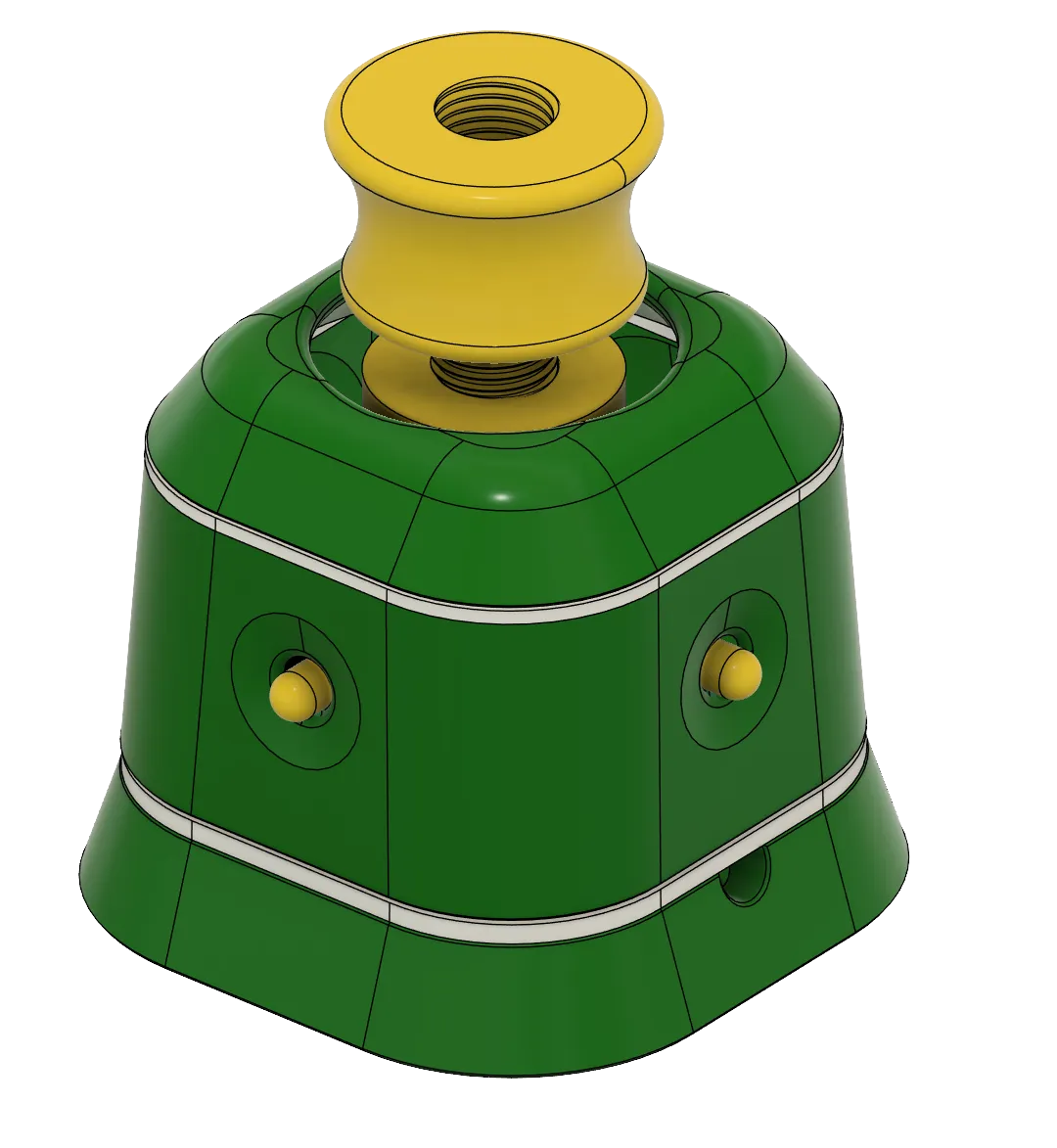
I wanted to try and make TeachingTech spacemouse remix-design as small as I could and try to stabilize the controls a little. The original was very soft and responsive, and the smallest movement would sent camera all over the place.
For more details about this design, code, how it works check: https://www.printables.com/model/864950-open-source-spacemouse-space-mushroom-remix
In order to achieve that I've experimented with two flat springs working as movement stabilizers. It was fairly successful, though the movement is more stiff now.
I'd imagine the springs design can be improved further.
Compared to original V2 minish, this design is noticeably smaller:

The joysticks had to be packed really tight and leaving their stick sticking out (the yellow caps on the photo) allowed to shave off some diameter.

There are no great changes to the arduino code - the copy provided here mainly differs by having deadzone updated and extra delay() call in main loop - which seemed to further stabilize the movement.
Still this remix is more of an experimental idea, and not a perfect product.
The two springs help stabilize the movement but at a cost of ease of operation.

The material from which spring was made can affect the entire feel and usability (try PETG or something equally strong and elastic).
The springs shape itself might not be best optimized for the use case at hand.
- For example there are 2 pairs of spring whiskers, which face opposite directions - this helped to stabilize the amount of force required to twist the joystick head / camera. -
- Basically both directions need similar amount of force, while when they faced single, the one was easier to twist than other.
Right now the bottom is slightly thicker than top (as it must hold the entire joystick in place) while top one should be softer so joy head movement translate better into rotation commands.
At the same time it makes harder to pan the camera to the sides, because spring tension or the small holes for joystick arms, can introduce accidental rotation.
With some practice the protruding buttons can be used for this case, though it’s easy to accidently click them, and as such it won’t work well in cases when they’re connected to the board.
Changing the joy head height can greatly affect how easy it’s to operate the device. That’s why it’s a threaded composition instead single solid piece. It's easier to find the sweet spot between spring tension and joy head movement.
The bottom could benefit from some extra weight or rubber feets, so it doesn’t move as much when we try to use the device.
The JoyShaft is probably as small as it can be with this amount of joystick modules - or analog joysticks in general. We could drop the board and use joysticks directly, but the x,y dimensions will be close to what’s already achieved. And deacreasing height might negatively affect the balance between shaft, springs and the joystick. Though it could probably shave off a centimetre or two.

Another approach could be dropping the prefabricated chasis and model a custom one for potentiometers - at least to get a 5-dof joystick, with 6 dimension being an extra one, translating to zoom (ie. push down).
We could maybe use 2 joysticks for directions, and something else for zooms (like HAL sensor, or optical slot sensor (like one used in pc mouse scrool wheels). Maybe in some future versions xd.
Instructions
Printing
- PETG or other material that works for 3d printed springs
- it must be elastic and resistant to deformation.
- it can not be brittle (that’s why PLA won’t work too well).
- Any other material for other parts.
- How pliable is the material can be affacted by incorrect nozzle temperature - make sure to use range suggested by the manufacturer.
- For example recently I’ve noticed that the Bambu Generic PETG preset might work fine for most, but the prints look and feel much better when printed in lower temps (per manufacturer).
- Too hot nozzle can make the filament stringy, introduce scratched like surfaces and make the model itself more brittle.
- This is especially important when printing objects like springs - which must survive many tension/release cycles.
- For example recently I’ve noticed that the Bambu Generic PETG preset might work fine for most, but the prints look and feel much better when printed in lower temps (per manufacturer).
- Try using transparent material for the springs
- This way they could work as light diffusers for the LEDs
- That’s the type I’ve used for test prints and even some cheap, generic transparent PETG worked quite well and the springs were able to take quite some punishment without braking.
- Not sure if pigment or any other additions might affect filament toughness. It’s more likely dependant on the manufacturer and the overall quality of the material itself.
- Joystick holes in middle cover might come out a little bit deformed - due to the overhangs. Any uneven surface should be filed down with high grid sandpaper. Unevenness is not a game braker, just make it as smooth as reasonably possible.
Additional parts:
Depending on how robust model you wish to build you can either use the fully 3d printable approach and use the provided Pegs or go with 4x 3Mx12mm and 4x 3M brass inserts.
Tricky things to remember:
Few steps can be tricky or easy to do in wrong order which takes us back a step. Be careful when:
- Adding joystick modules in JoyShaft
- They must go in the presented order, otherwise their axis will be out of sync
- In case the boards you got are a too wide you can easily trim excess from the sides without affecting it (the actual circuits are few and don't run near the edges)
- Guiding cables through JoyShaft holllowed out space can be a bit tricky (especially if you don't wish to desolder the default pins)
- It gets easier with practice, but better to double check whether all cables are accounted, connected and lead through the bottom exit (where joinable screw will clamp around them).
- Bottom spring and joinable screw
- FIRST spring, and THEN the screw
- this is especially important if you want to guide cables through it
- (how do you think it became a joinable screw instead solid model xD)
- Once you get the bottom cover screwed to the middle section it's harder to take it apart
- Make sure the JoyShaft has enough space to go down and no cables or arduino board are restricting its movement.
- Small resistance from the cables will be fine. It's still far from being precise instrument.
Assembly
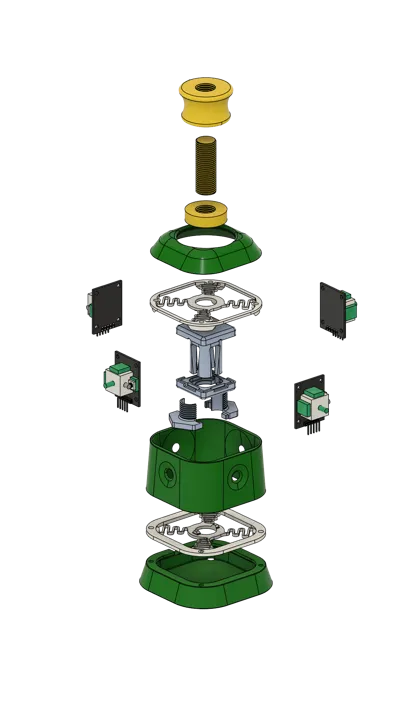
First let's start with getting the joystick modules mounted on the JoyShaft
First we begin with the main body and start adding Joystick Modules in the presented orientation and position.


The pins should point upwards:

Each modules should overlap another one (ie. 1st module side with a button, must cover 2nd module butonless side).

- The modules must go in the presented order, otherwise their axis will be out of sync
- In case the boards you got are a too wide you can easily trim excess from the sides without affecting it (the actual circuits are few and don't run near the edges).
- Check the top side of the covering cap, it has small embossed dots, that should indicate where the button side goes.
----
Cable management
This is a moment to guide through the cables through the openings in the main body. It’s possible to use regular arduino cables with joystick pins as is, without soldering. It might take few triesa and practice. We’re really trying to squeze things here to save space.

This is an older iteration, but the cable management is basically the same. We can use the mounting holes on the joystick module to guide the cables through - but they might need to be widened a little.
NOTE: Try using distinct colors for each joystick module. It’ll make connecting everything to microcontroller much, much easier.
Example (as on the picture):
- cold colors for X axis, warm for Y axis.
- Or warm/cold colors on the opposite sides of the joyshaft, never to the closest neighbour.
- Only reds or blacks for vcc and gnd.
----
After getting them in place, put on the cap and push, there might be some resistance, but it means it works and the joystick modules we’ll be sitting tightly (but be carefull, not to impale your fingers on the sticking out pins 🥲)

Now FIRST we must add the bottom spring (and guide cables through it) and THEN we use joinable screw to hold everything together.
Both springs have guiding extrusions which fits the JoyShaft top and bottom parts.
The joinable screw should keep the spring firmly in place but don’t put too much force on it. At the same time the spring can not be skewed to any of the sides. Its sides must be pararel to the joy shaft sides - as in the picture:

In the end it might look a bit like here:

At this stage you might need to choose how you’ll connect the middle cover to the joys w/ spring.
The most robust approach is to use M3 brass press-in nuts.
Or (for temporary or often dissasembled cover) use 3d printed pegs, that keep the parts so so together.
Either way the next step is th same, putting the middle cover over the joysticks. Easiest is to turn one of the parts 45 degrees, so joystick arms fit in cover rouned corners, and then twist until the click into the holes.
And these modules can take quite some punishment without any side effects, so they’ll survive.

----
Fitting in the board
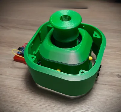
At this point you might start to think how you’ll fit the arduino board inside the bottom cover. To achieve that you’ll most likely need to use solder. The goldpins are just too high for this design.
In order to just play around with the model, the board can be just kept outside and it’ll work fine as well :)
The board seems to deal well enough, powering the 4 joystick modules. So no extra power lines will be required. (For arduino pro micro board (or a lookalike)).

Making the bottom cover bit higher could help fit everything inside more easily, but it would make the whole device bit too tall (IMO it’s still too tall to operate already).
Let’s say the miniaturization hasn’t been fully achieved in this version xD
----
Use 3M screws to get the bottom and middle parts together (or use 3d printed pegs).
At this point you can mount the joystick caps.

Now it’s time to get the top spring in place. It has similar fit/lock extrusions as the bottom spring.
The top spring has these small wings, that should push a little into the rounded corners of the middle cover. It helps to keep the spring in place. But most of the work will be done by the joystick head base.
At this time we can put in the joystick head main screw.

Now screw in the joystick head base, untill it fits snuggly over the spring (don’t overturn or it’ll skew the top spring!)

The top cover can be attached to the top spring via 3d printed pegs. They seem to suffice in keeping these parts together.
Using screws and brass press-ins would be a bit harder here - as the top cover is relatively thin.

Last part is the joystick head. It’s on thread as this method really helps in finding the right distance between the head and the springs.
It’s more of a prototyping solution, and can be easily replaced by merging the models before printing.
CABLES CABLES CABLES
Now the worst / easiest part.
For the most part the connection is same as shown in Teaching Tech project doc, but reversed.
In short - there are no changes to the mapping in the code. We just swap physical connections.
Joystick modules switch places with eachother:
C → A
D → B
The left side of the device (USB port facing fowards) will be connected in order of - yx, yx.
And right will follow - xy, xy
Basically this:

If something behaves weirdly, just recheck the connections, or switch them around untill they start to operate correctly :D
(it’s faster than reassigning or mass replacing variables in the code)

Comment & Rating (0)