
Robotic Arm 3 Axis Connected
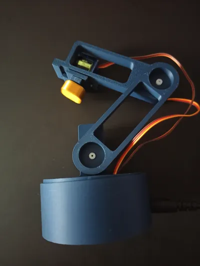
Print Profile(1)

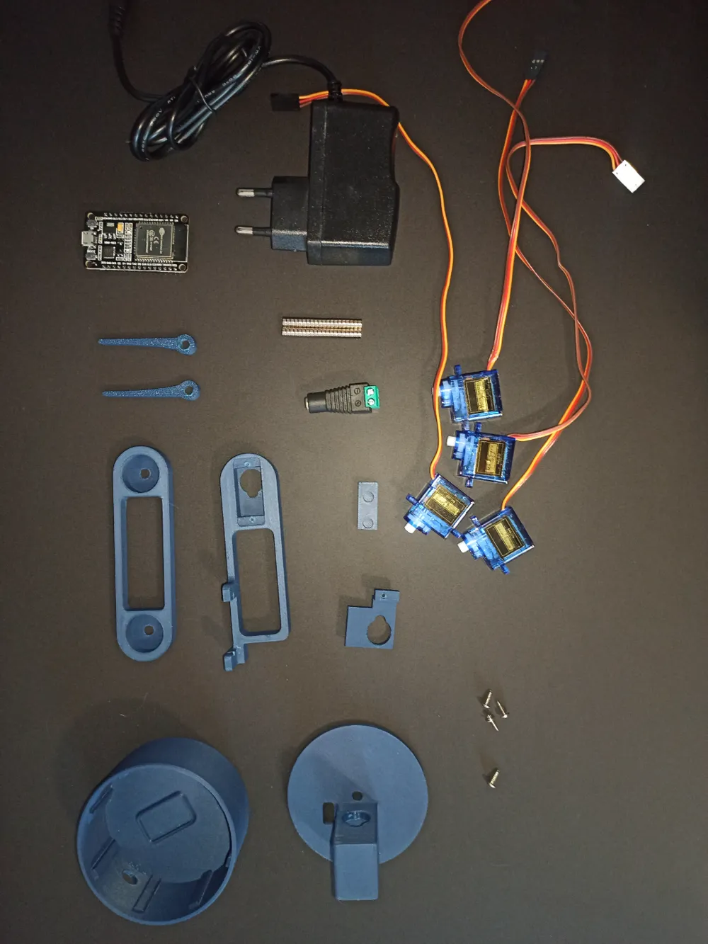
Bill of Materials

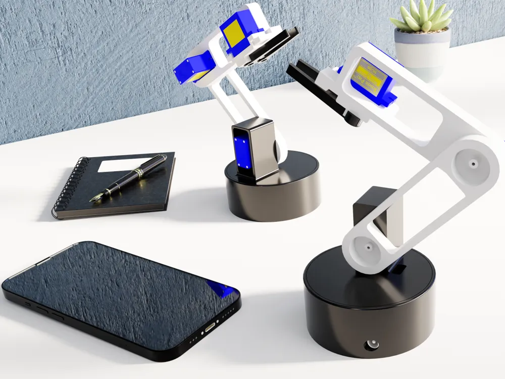
Description
Boost Me (for free)
If you wanna support me and my project (especially the one....) !!!!!
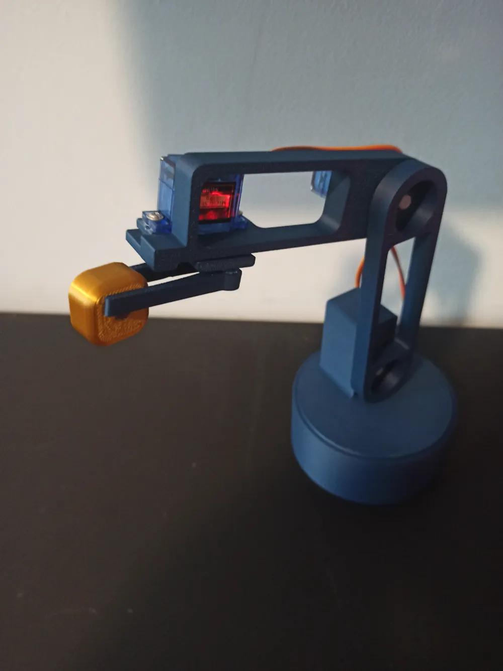
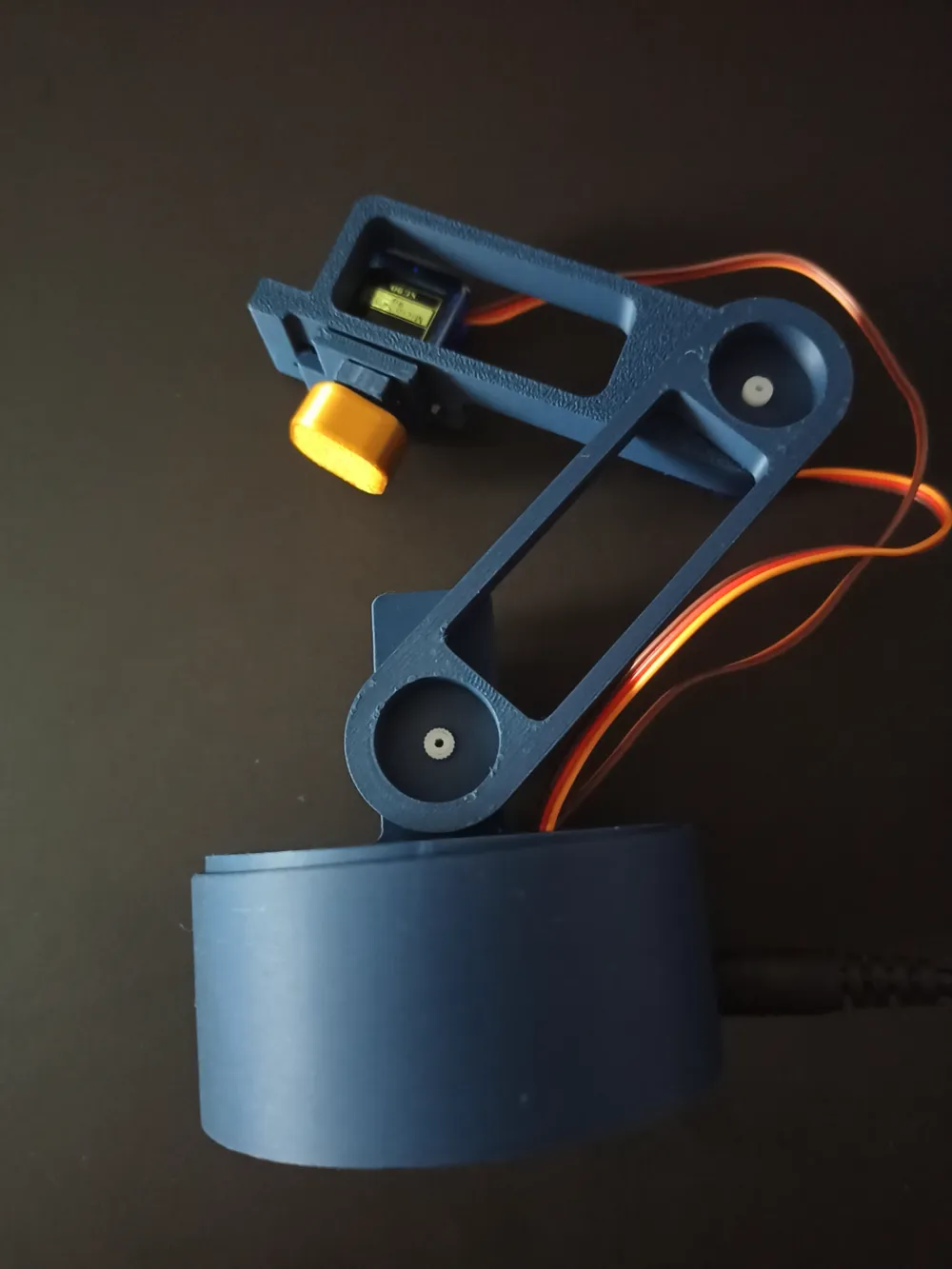
Warning: This robotic arm remains somewhat fragile as it uses SG90 servo motors. Additionally, the project can still be improved in its design (maybe for next time...).
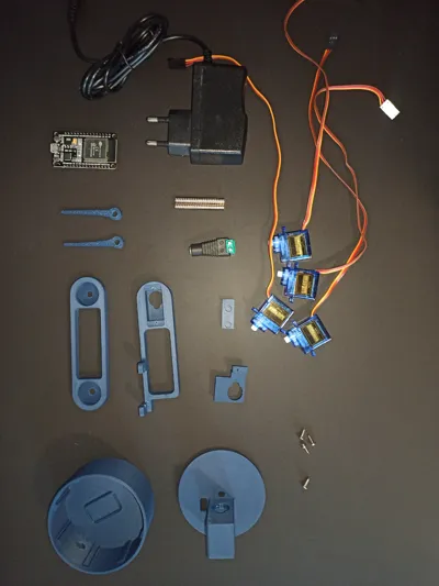
Components for the connected robotic arm:
- 1 ESP32
- Female jumper wires
- 4 Servo motors
A female jack connector
THE WHOLE PROJECT IS ON GITHUB (for more details): Github Project Link
Step 1: Install Base Servo Motor Step 2: Mount Servo on Circular Plate Start by taking the circular base and installing a servo motor in the center. ⚠️ Do not screw it too tightly. Next, take the circular plate, place a servo motor on it, and pass its cables through the designated slot. 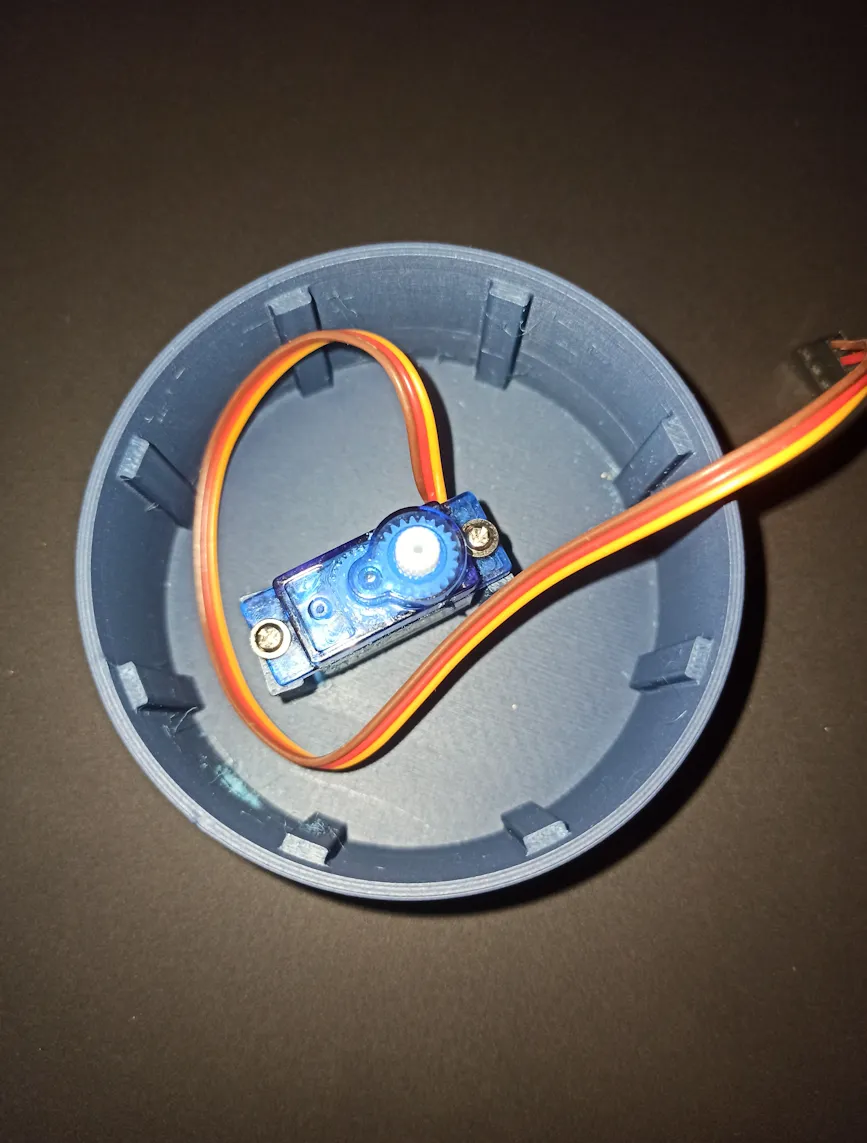
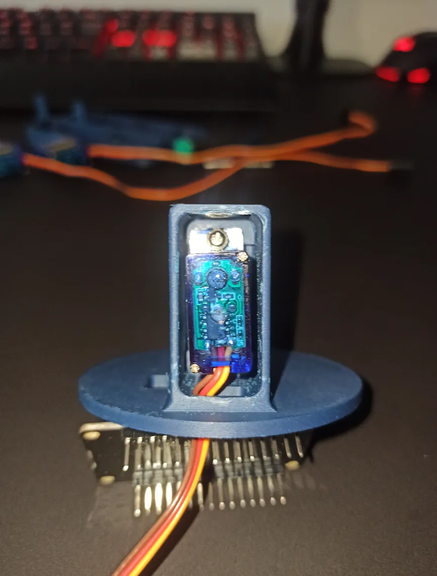
Step 3: Assemble Second Arm with Support Step 4: Connect Arms to Base Assemble the second arm with the small support and a servo motor. ⚠️ Do not tighten the screws too much. Attach the first and second arms together, then mount everything onto the servo motor of the circular base. 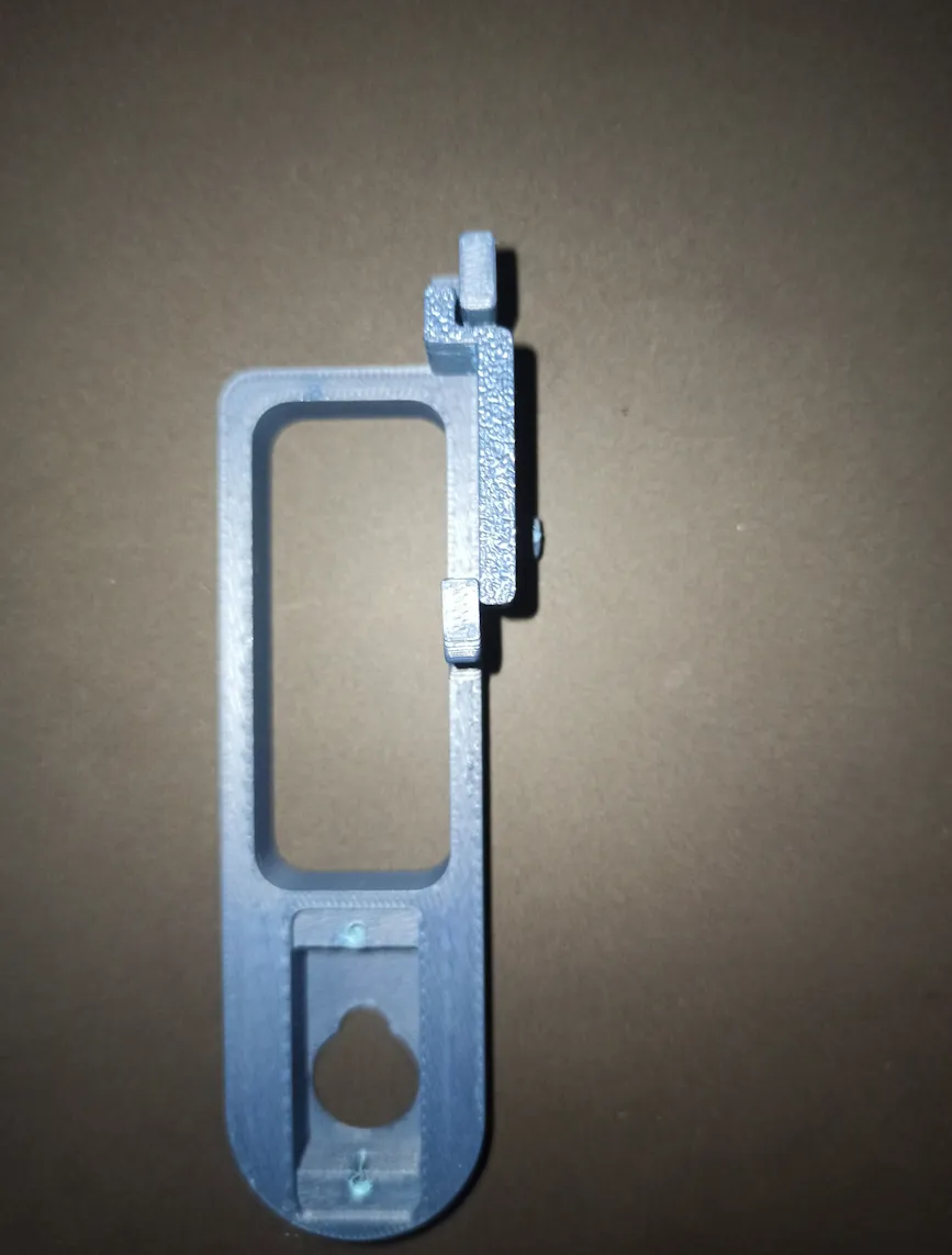
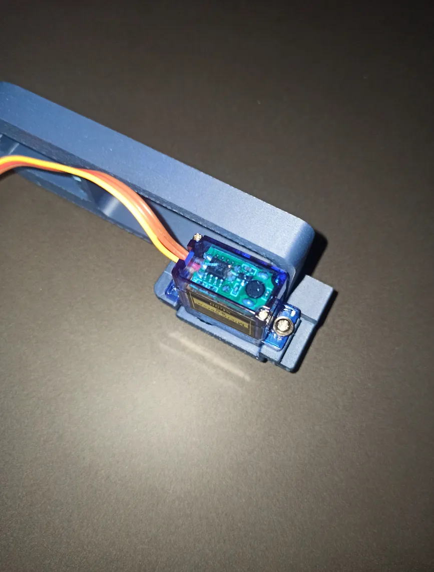
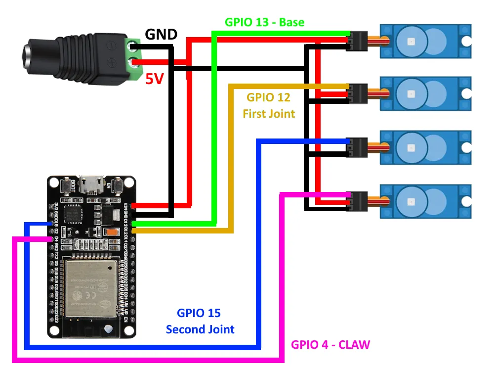
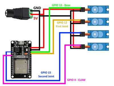
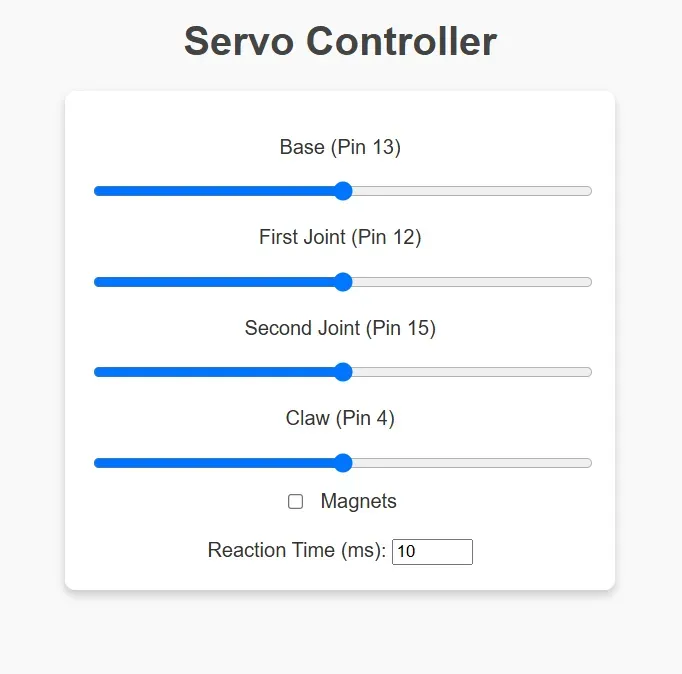
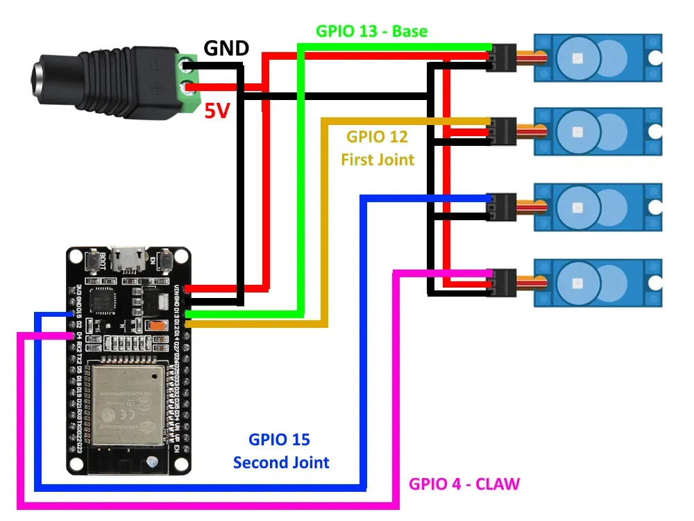
Step 5: Wire Everything and Upload Code Step 6: Test via Web Interface 1. Upload the code to the ESP32 2. Find the IP address via serial port or Advanced IP Scanner 3. Connect all wires properly (+5V, GND, servo data cables) ⚠️ Use short cables to avoid issues. Open a web browser, type the IP address, and test! ⚠️ If using magnets version, check the box. Adjust servo reaction time to modify rotation speed. Close the assembly and choose clamps or magnet support. 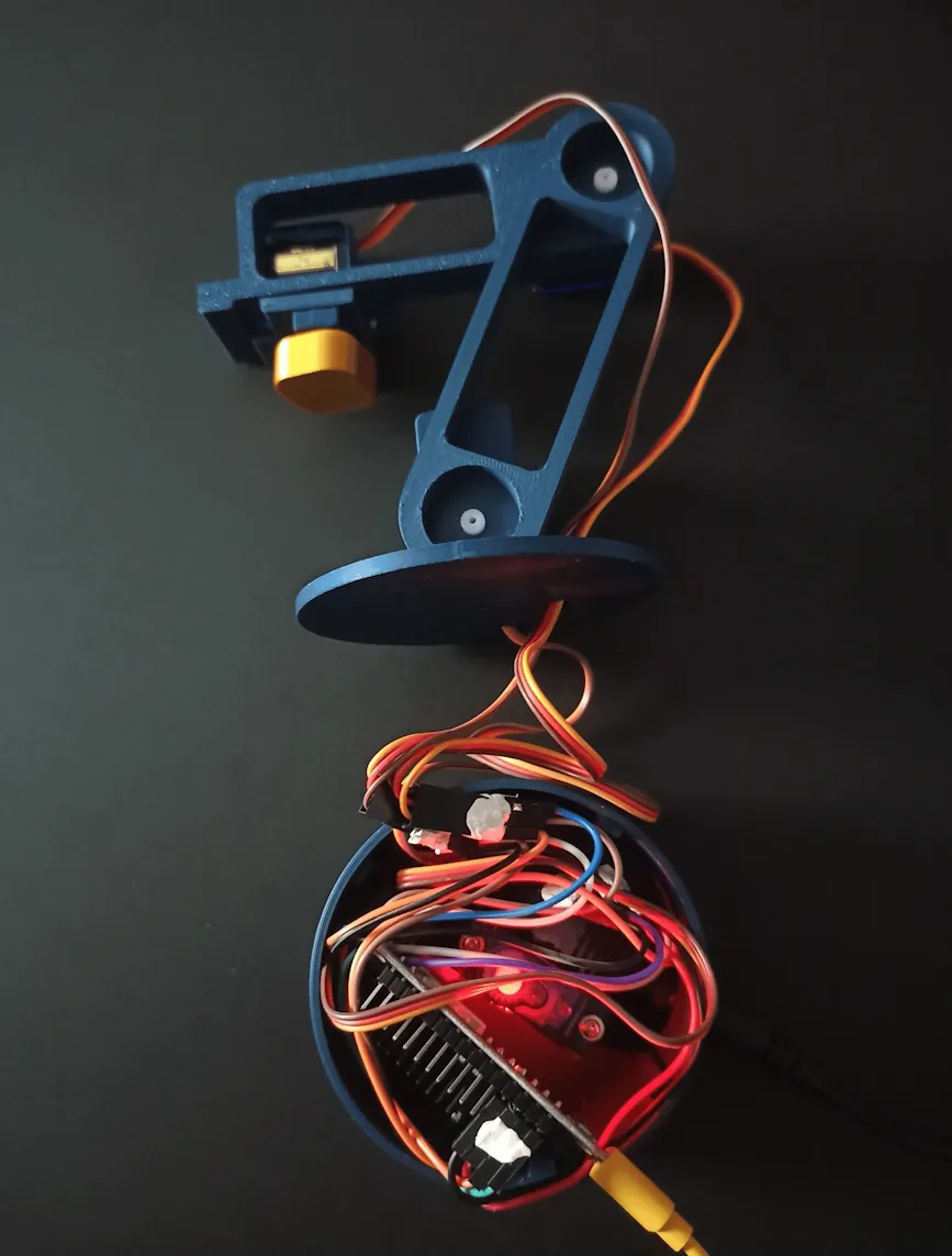
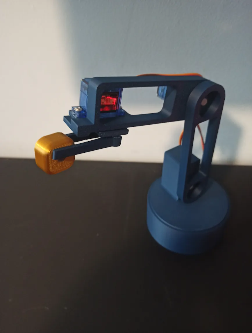
| Web Interface | Electronic Schema |
| Control panel for managing servo motors and settings. | Wiring diagram for proper component connections. |
 |  |
License

You shall not share, sub-license, sell, rent, host, transfer, or distribute in any way the digital or 3D printed versions of this object, nor any other derivative work of this object in its digital or physical format (including - but not limited to - remixes of this object, and hosting on other digital platforms). The objects may not be used without permission in any way whatsoever in which you charge money, or collect fees.


Comment & Rating (141)