
Second Version of 2S Brushless Handheld Polisher
Print Profile(2)

Description
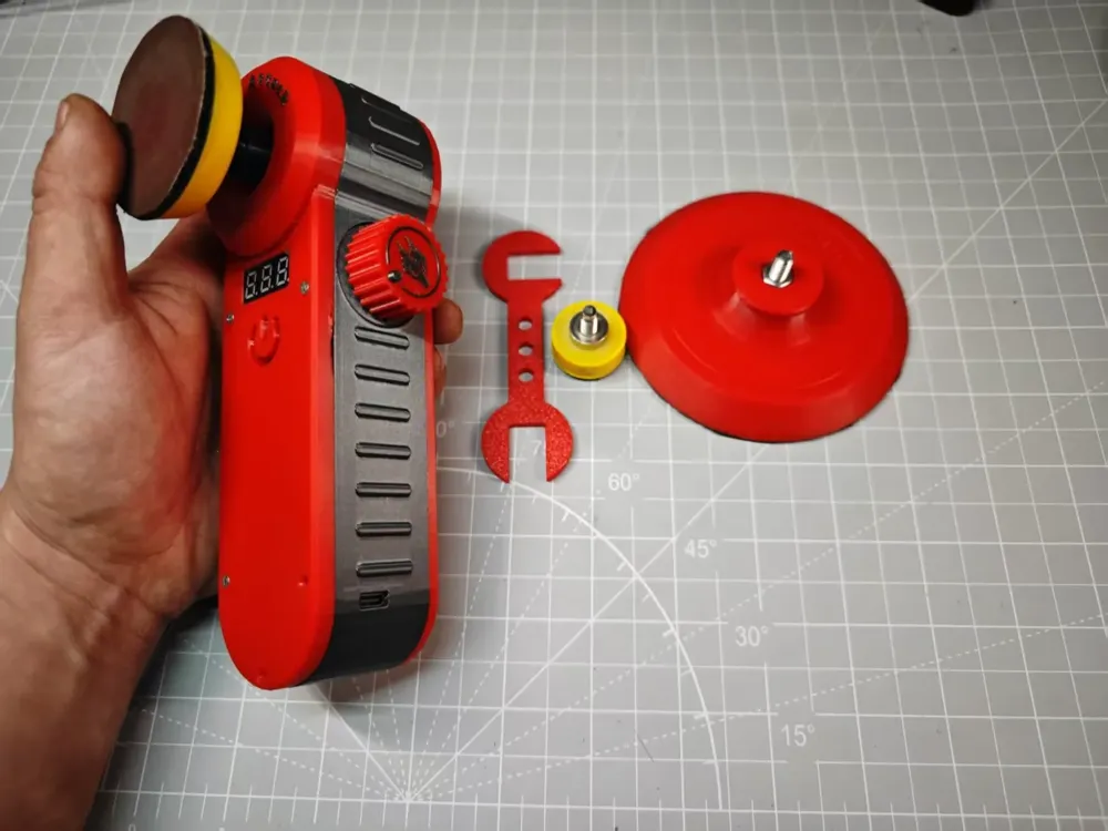
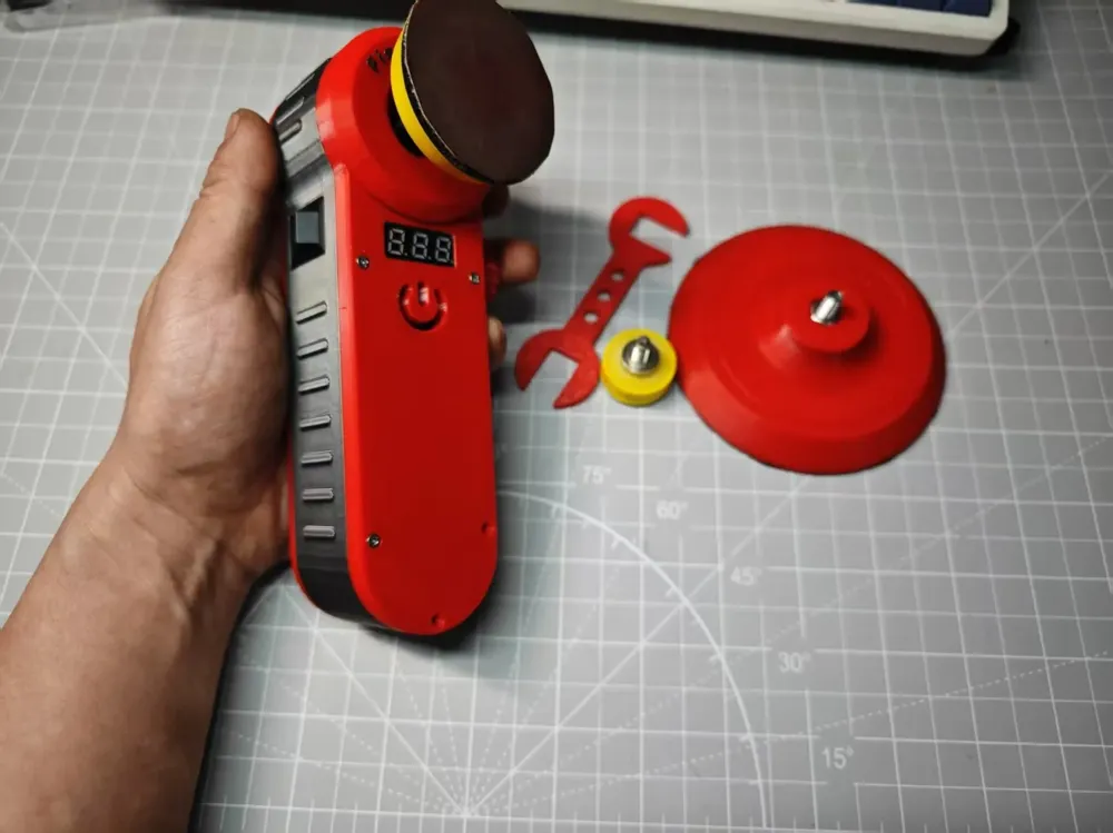
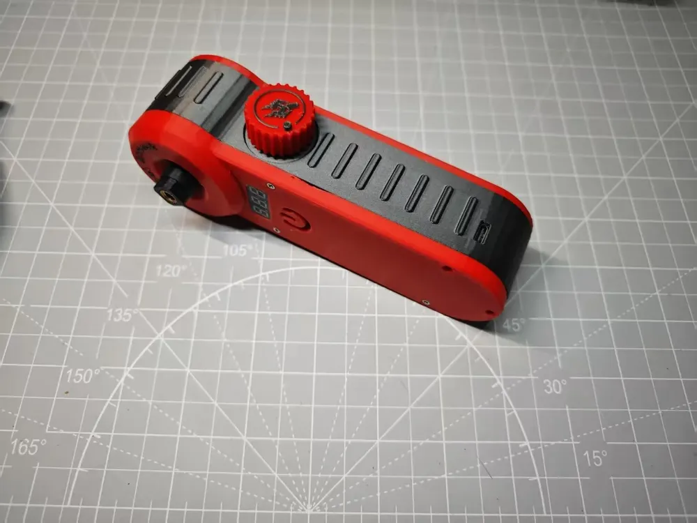
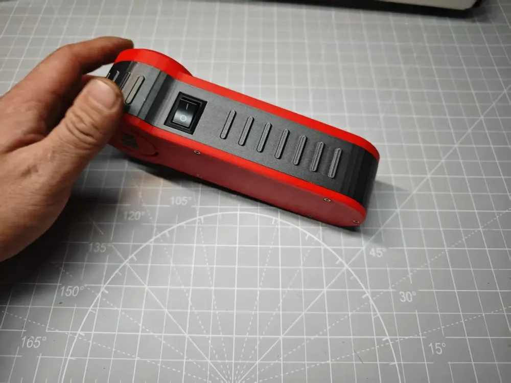
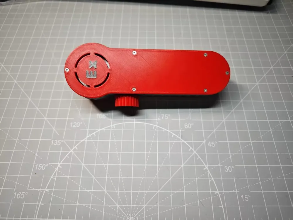
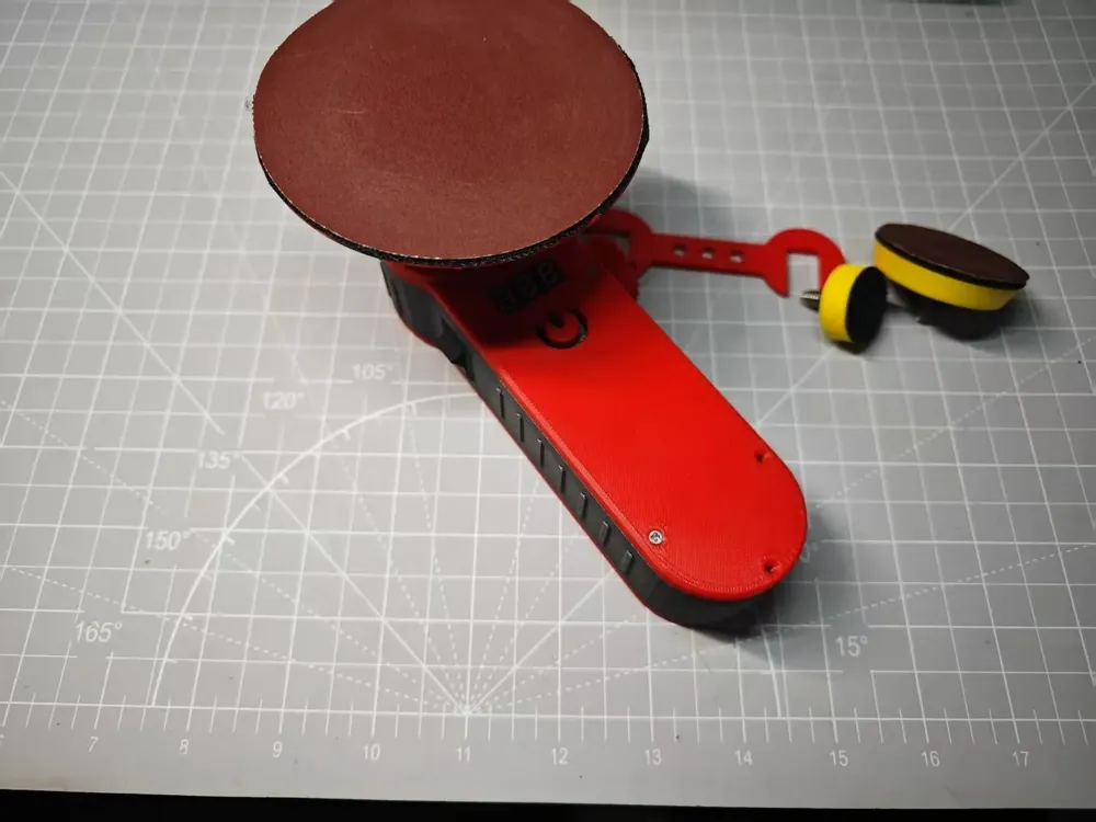
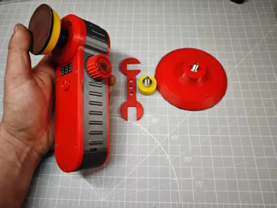
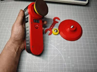
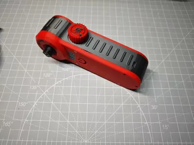
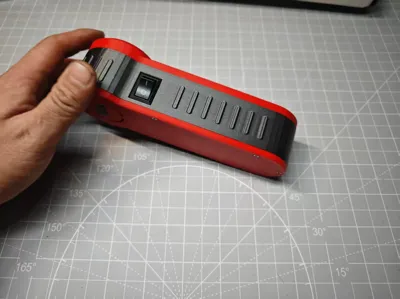
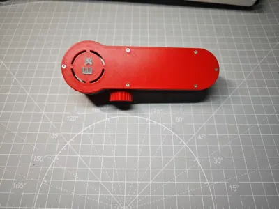
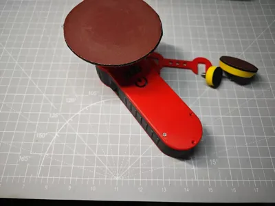
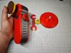
Second Generation Brushless Handheld Polisher
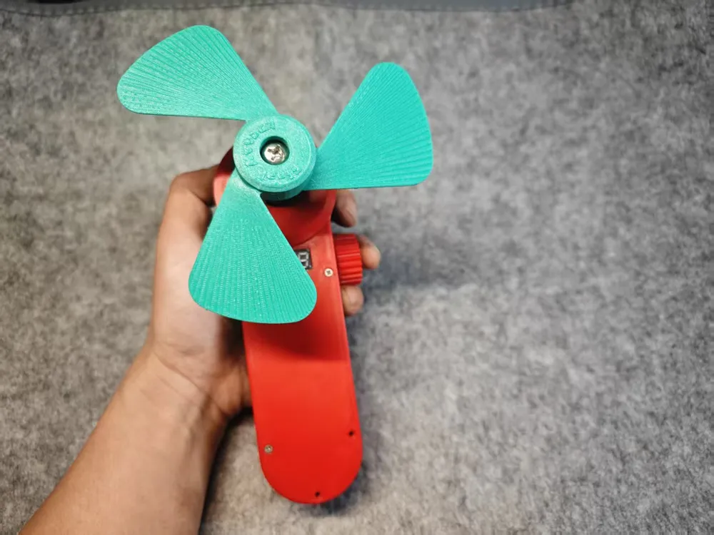
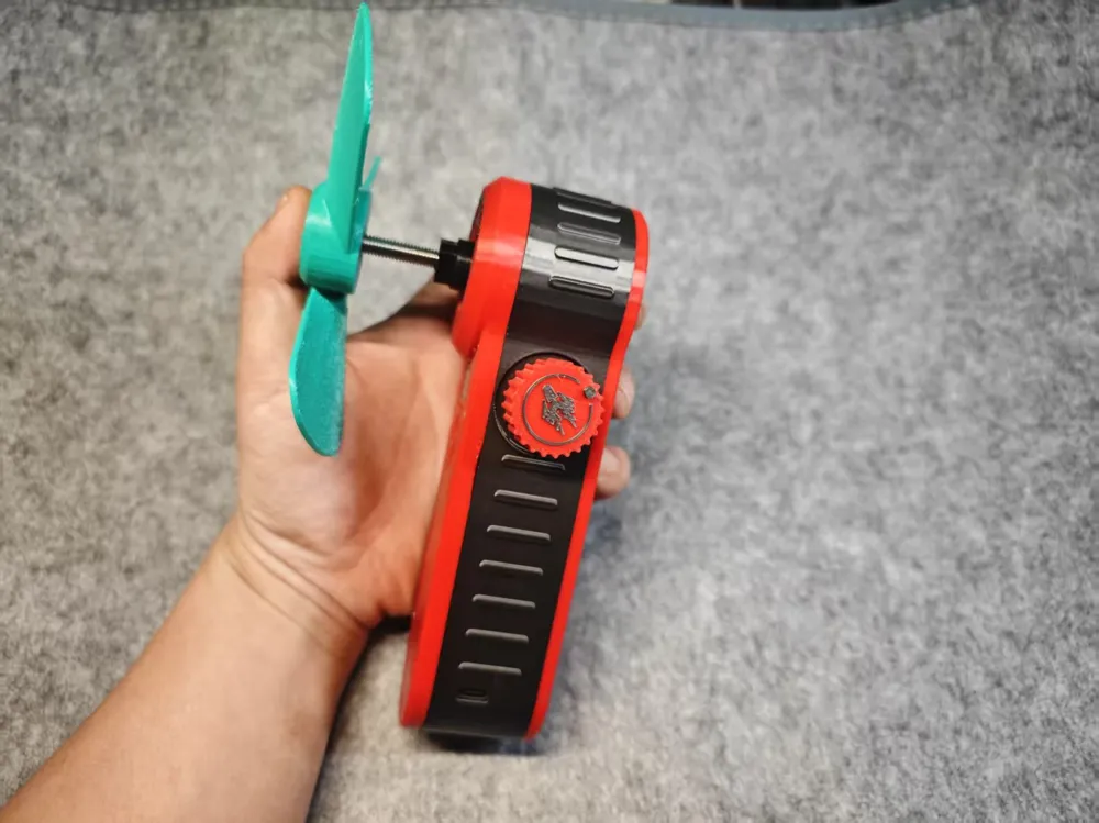
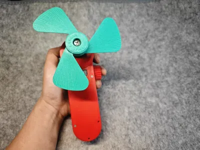
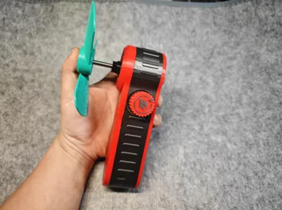
April 9th Update: Added a matching integral impeller. An M6*40 screw and nut are required; I currently only have this length screw, but an M6*20 or longer screw will suffice. The impeller provides airflow, though not as powerful as anticipated—purely for aesthetic effect.
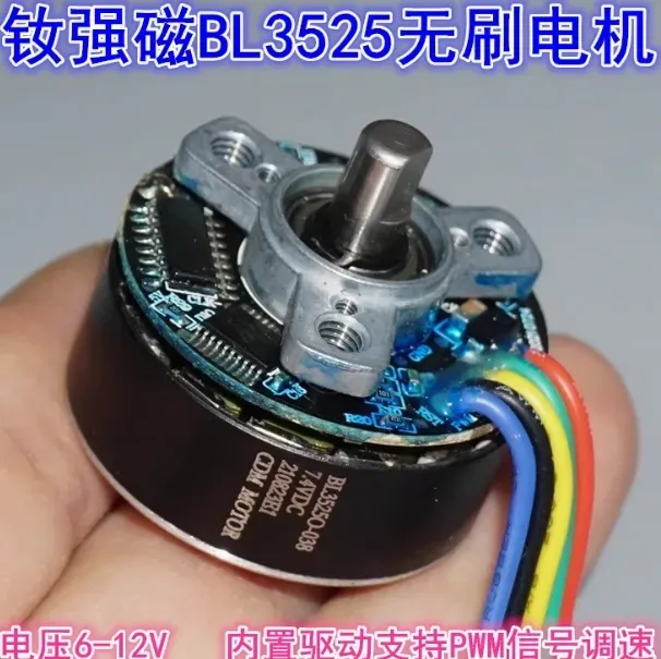
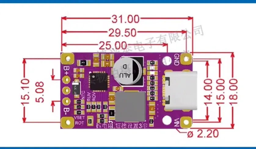
The motor has been upgraded to a similarly sized brushless motor with a strong neodymium magnet drive, eliminating the need for bearings. The DC charging port has been replaced with a dual-series boost fast-charging module, enabling charging via a standard mobile phone charger.
Important Notes:
1. Connect pins 1 and 2 of the potentiometer to the black negative terminal of the motor, and pin 3 to the blue PWM speed control terminal of the motor. Connect the positive terminal of the battery protection board to the switch; connect the other terminal of the switch to the red positive terminal of the motor. Connect the negative terminal of the battery protection board to the motor's negative terminal. Connect the positive and negative terminals of the voltmeter in parallel to the positive and negative terminals of the motor. Connect the positive and negative terminals of the battery protection board to the B+ and B- terminals of the dual-series boost board for charging. For reference only; not professionally engineered
2. The motor shaft is custom-made; before installation, trim the M2 self-tapping screw to the appropriate length. Reinforcement with adhesive, such as epoxy or casting resin, is recommended.
3. The first half of the 10K potentiometer's range is insensitive, preventing precise speed control. A 5K or 20K potentiometer may yield different results. A future iteration will eliminate the speed control casing; at low speeds, precise speed adjustment seems unnecessary.
4. The fastening screws are M4*5 (omitted from the table below)
Installation video reference:
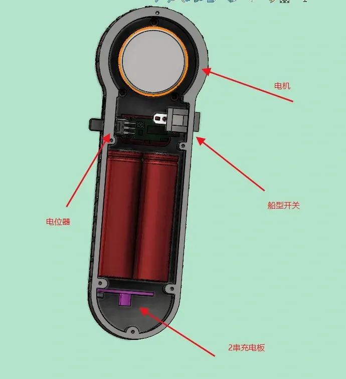
Internal diagram reference:
Motor reference diagram:
Use the purple dual-series boost fast-charging board shown below; secure it with hot glue after ensuring proper fit.
Required Components:
| Neodymium Magnet BL3525 External Rotor Brushless Motor | With Integrated Driver | 1 |
| 10K Potentiometer | For Motor Speed Control | 1 |
| M2*8 Self-Tapping Screws | For Casing | 14 |
| 2-inch/1-inch Polishing Pad | M6 Screw Mount | 1 |
| Dual-Series Boost Fast-Charging Board for Lithium Battery Packs | Purple Version for 2-Series Batteries | 1 |
| 2-Series 8.4V Lithium Battery with Protection Board | Main Battery | 1 Set |
| 0.28-inch Voltmeter | For Battery Level Indication | 1 |
| KCD1 Two-Pin Rocker Switch | Main Power Switch | 1 |
| M2*6 Self-Tapping Screws | Trimmed for Motor Shaft | 2 |
| 304 Stainless Steel Screws and Nuts | For Custom 4-inch Abrasive Disc | 1 Set M6*20 with Nuts |
| Self-Adhesive Hook and Loop Fastener | Hook Side | |
| Knurled Nut M6*10*8 | For Motor Shaft |
License

You shall not share, sub-license, sell, rent, host, transfer, or distribute in any way the digital or 3D printed versions of this object, nor any other derivative work of this object in its digital or physical format (including - but not limited to - remixes of this object, and hosting on other digital platforms). The objects may not be used without permission in any way whatsoever in which you charge money, or collect fees.


Comment & Rating (0)