PS4 Controller-Operated Robotic Dog


Print Profile(1)

Bill of Materials

Description
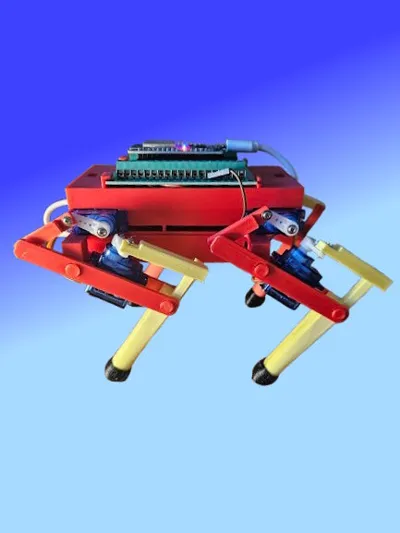
Fully functional robodog powered by ESP and 8 servos, controlled with a Playstation 4 controller.
Technical Details:
- Controller: PS4 DualShock 4
- Control: Bluetooth connection to an ESP32 microcontroller
- Servos: 8 servo motors (two for each leg)
- Material: PLA
- Software: Arduino IDE
Functions:
- Move forward, move backward
- Rotate in place
- Sit down, stand up
- Precise and responsive control via the PS4 controller.
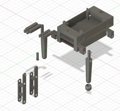
Parts List:
- 1x ESP32 Devboard
- 1x 30-Pin Adapter (for screw terminals on the ESP)
- 8x SG90 Servo Motor
- 1x Battery (optional, another power source can also be used)
- 1x USB Cable (PC connection -> ESP)
- 1x PS4 Controller (For controller control)
- Jumper Wires
- Software:
Arduino IDE
Wiring Instructions:
- Power Supply for Servos:
- All positive wires (red) of the servos are connected together and then connected to the +5V line of your USB power source (power bank or power supply).
- Ensure that the USB power source provides sufficient current, as several servos are operated simultaneously.
- Common Ground (GND):
- All ground wires (black) of the servos are also connected together.
- Connect the common ground to two further points:
- The GND line of the USB power source.
- A jumper wire leads from the common ground (GND) to a GND pin on the ESP32.
- This connection ensures that the servos and the ESP32 have the same ground, which is necessary for correct signal transmission.
- Control signals of the servos:
- The control signals (orange or yellow) of the servos are each connected to a separate GPIO pin of the ESP32.
- If you use the following sketch, you can connect the servos as follows:
- Servo RHU; // Rear Right Shank PIN2
- Servo RHO; // Rear Right Thigh PIN4
- Servo LHU; // Rear Left Shank PIN5
- Servo LHO; // Rear Left Thigh PIN18
- Servo RVU; // Front Right Shank PIN19
- Servo RVO; // Front Right Thigh PIN21
- Servo LVU; // Front Left Shank PIN22
- Servo LVO; // Front Left Thigh PIN23
- You can adjust the pins according to your code, but make sure they are defined as PWM-capable pins.
- ESP32 Power Supply:
- The ESP32 is also powered via the USB power source.
A very good video on setting up the ESP for connection to the PS4 controller can be found here:
https://www.youtube.com/watch?v=EEViXFoSzww
Tip: Initially, I used a USB connection as a power source for testing purposes. When I later used the battery, I noticed that the running behavior changed due to the weight of the battery and had to be adjusted slightly. The exact location of the battery also plays a significant role. (I use this battery https://www.amazon.de/dp/B08VRL66HZ?ref=ppx_yo2ov_dt_b_fed_asin_title&th=1) and placed it as far forward as possible.
Documentation (1)
License
You shall not share, sub-license, sell, rent, host, transfer, or distribute in any way the digital or 3D printed versions of this object, nor any other derivative work of this object in its digital or physical format (including - but not limited to - remixes of this object, and hosting on other digital platforms). The objects may not be used without permission in any way whatsoever in which you charge money, or collect fees.
Comment & Rating (22)