
Split-Flap Clock Digit Unit
Print Profile(2)


Bill of Materials



Description
Split-Flap Clock Digit Unit
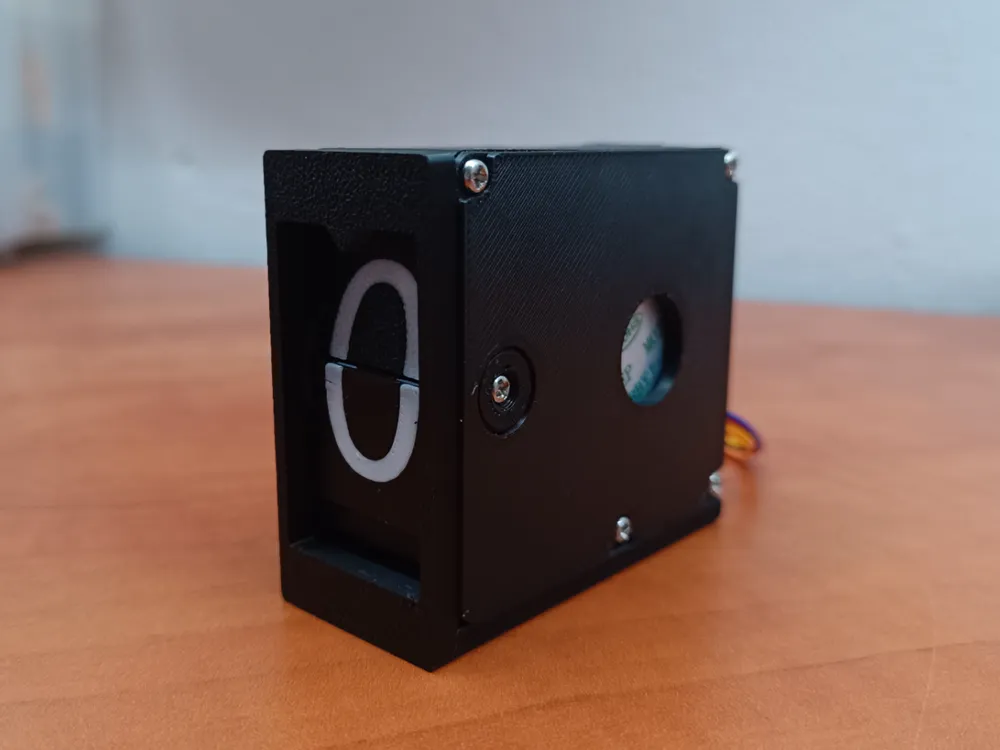
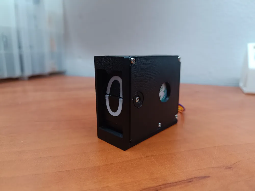
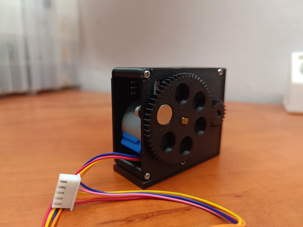
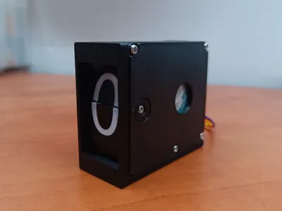
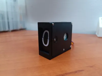
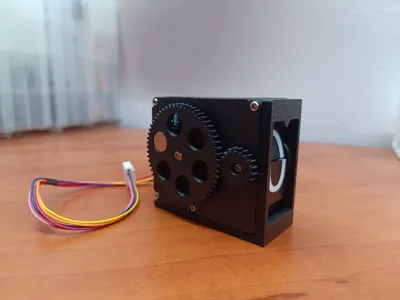
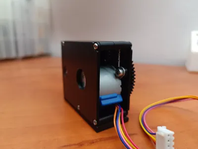
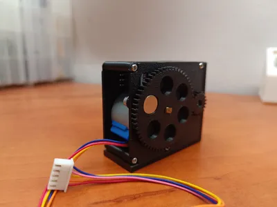
Bring your vintage clock project to life with this 3D-printed digit unit for a split-flap clock! This design serves as the foundation for a complete retro-style clock, integrating precise components for smooth and reliable flipping action.
Key Features:
- Designed as a base for a fully functional vintage split-flap clock
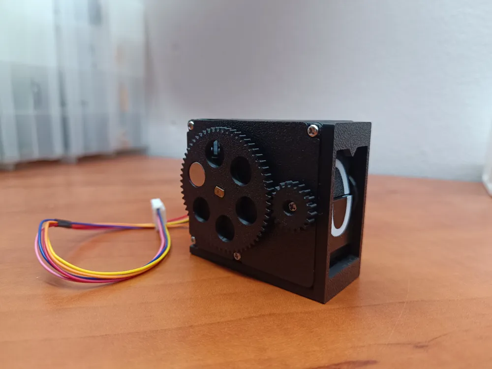
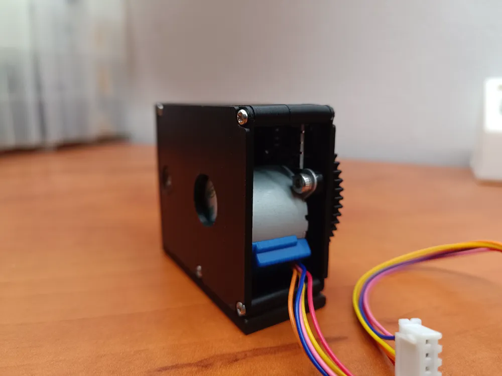
- Compatible with the 28BYJ-48 stepper motor for accurate and controlled flap movement
- Utilizes a KY-035 hall effect sensor and a 10x3mm magnet for precise positioning and calibration
- Modular and scalable for creating multi-digit clock setups
- Supports easy insertion and alignment of flap cards
- Robust and compact design for durability and easy assembly
Recommended Print Settings:
- Material: PLA
- Layer Height: 0.20 mm
- Infill: 20-30%
- Supports: Minimal, only where necessary
Files Included:
STL files for precise printing
Instructions:
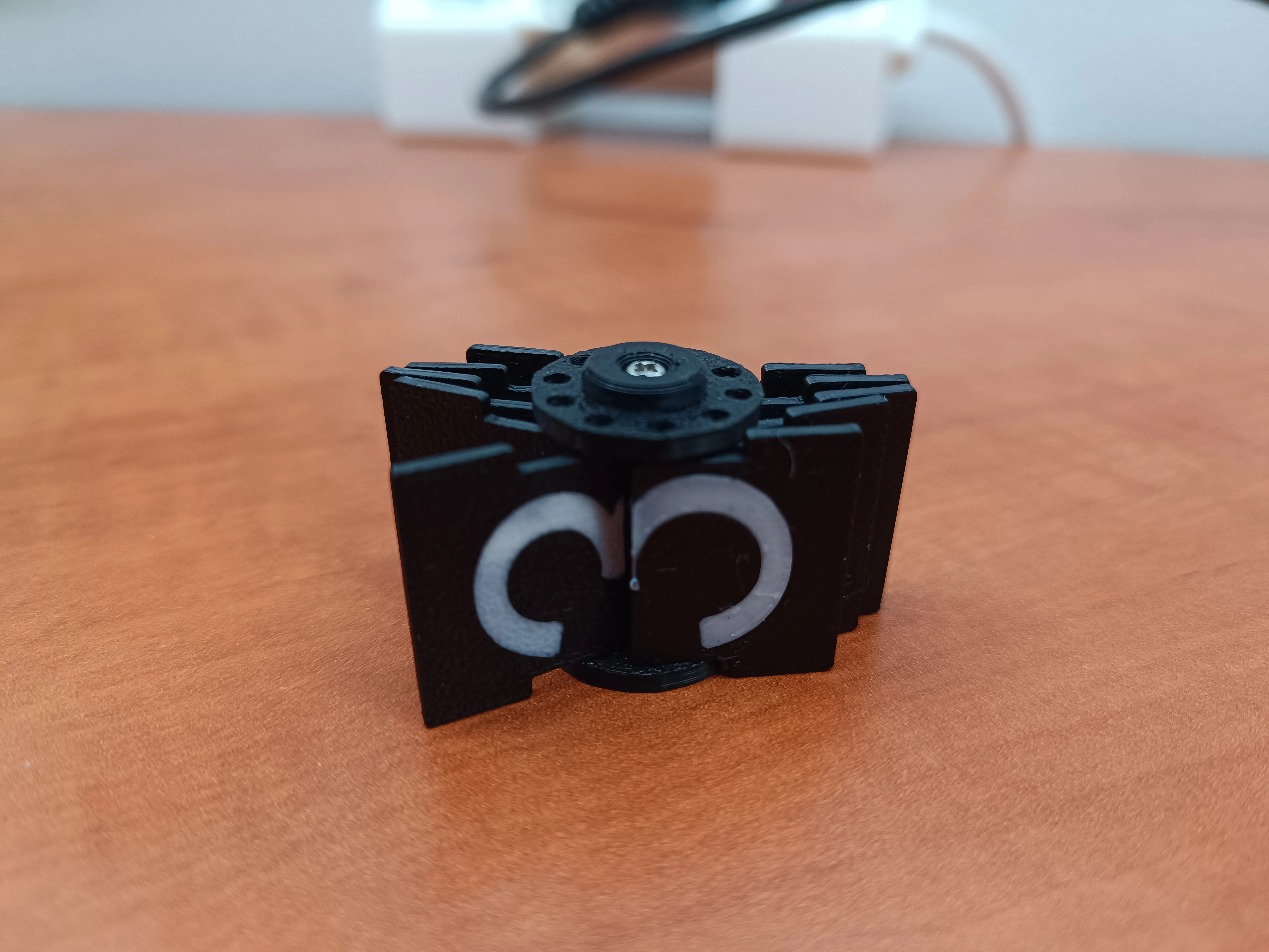
- Step 1: Insert two M2 inserts into the shaft of the wheel part. Press the wheels onto the shaft and clamp the digit flap in place. Refer to the included picture for proper orientation.
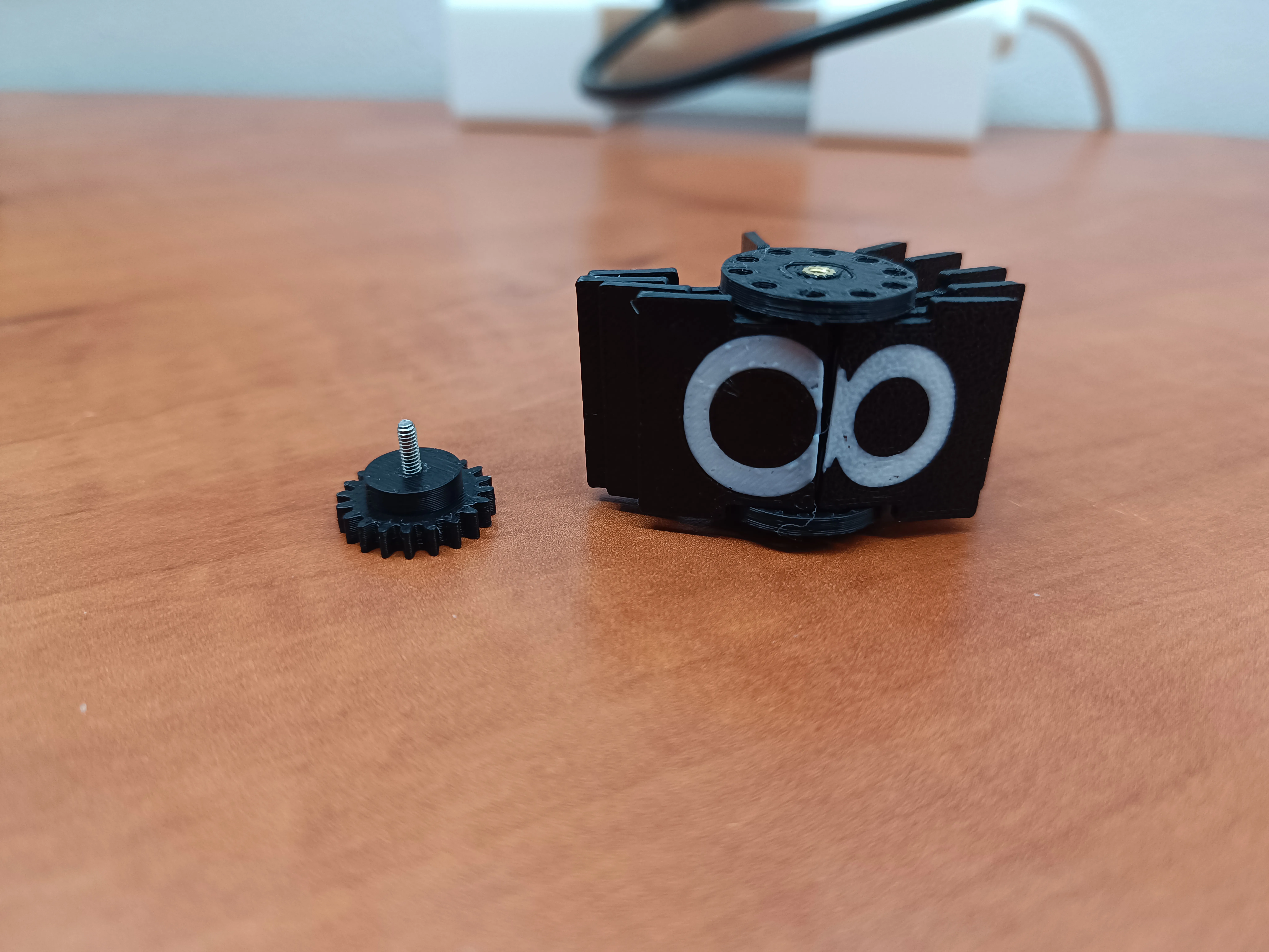
- Step 2: Mount the cap on the right side of the wheel using an 8 mm M2 screw. Then, press another 8 mm M2 screw through the small gear, but do not yet connect it to the assembly.
- Step 3: Insert two M2 inserts and two M3 inserts into the left wall. Ensure they are properly aligned for smooth assembly with the corresponding parts.
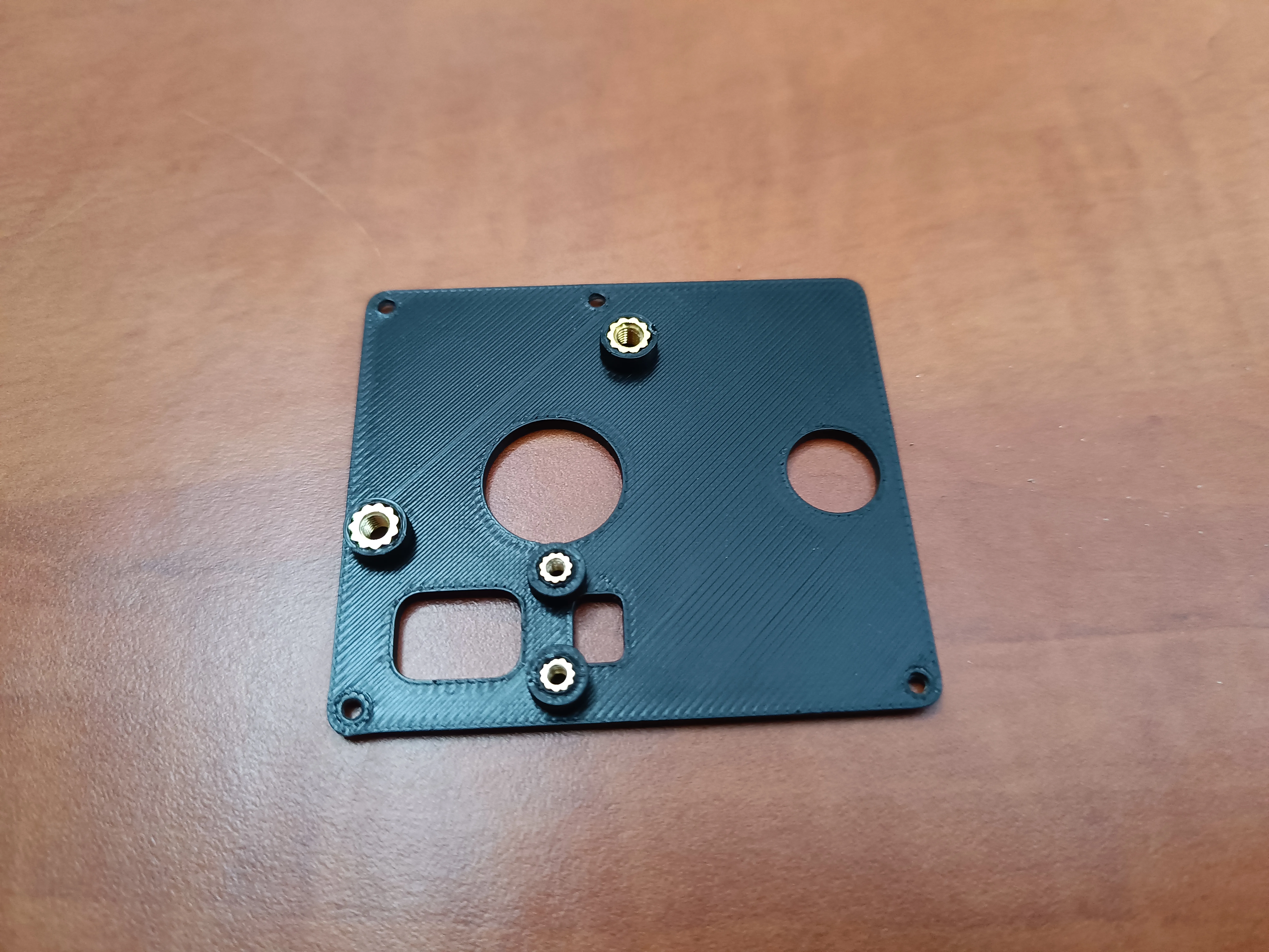
- Step 4: Use the 3 mm M2 screws to connect the KY-035 hall sensor to the designated mounting points on the assembly.
- Step 5: Use M3 screws to secure the 28BYJ-48 stepper motor to its mounting area. Ensure the motor is positioned correctly for smooth operation of the mechanism.
- Step 6: Pass the flap wheel assembly through the small hole in the left wall, ensuring the shaft is aligned with the appropriate slot.
- Step 7: Attach the small gear to the flap wheel assembly, securing it with the 8 mm M2 screw.
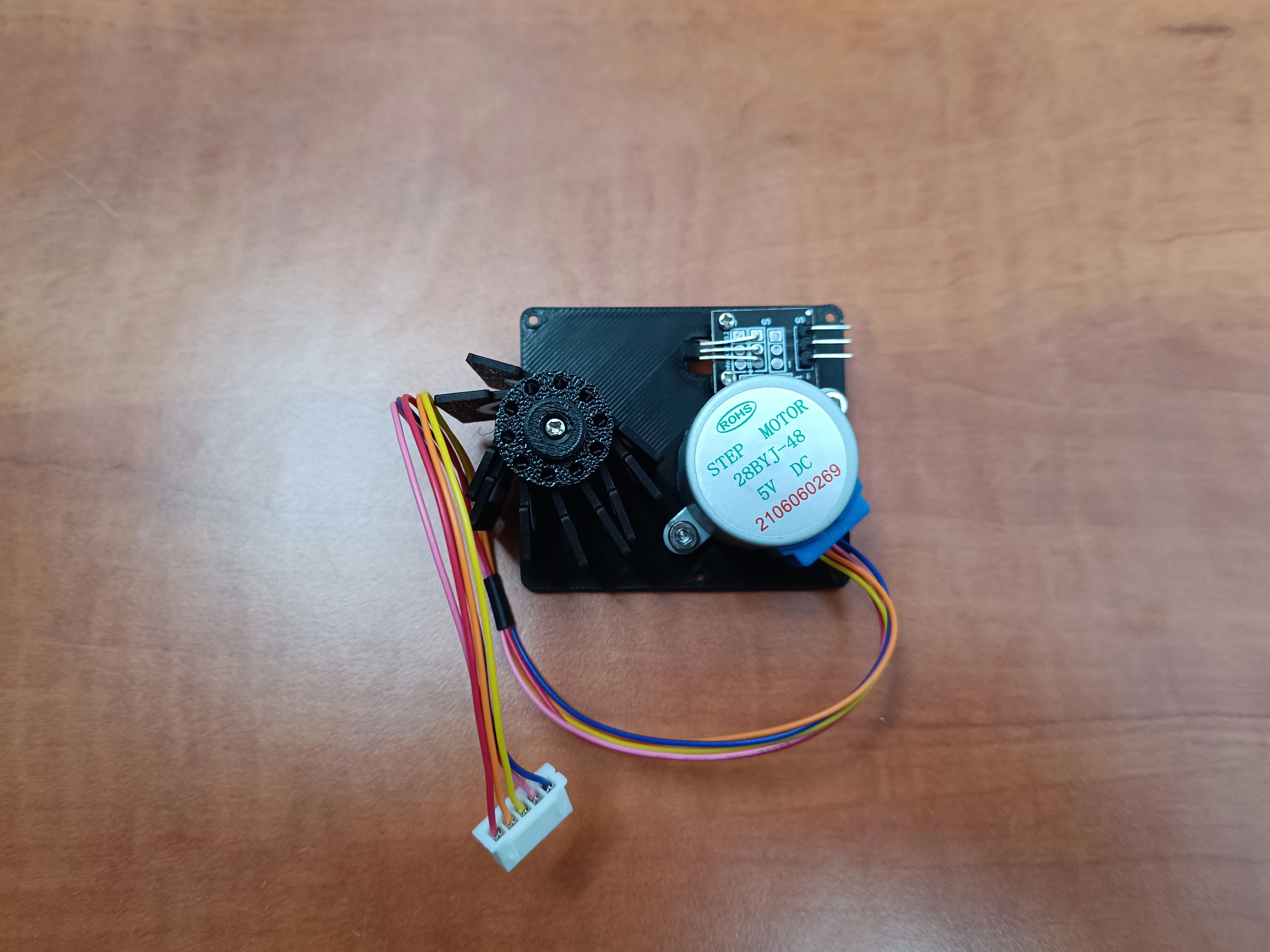
- Step 8: Insert eight M2 inserts and two M3 inserts into the top and bottom walls.
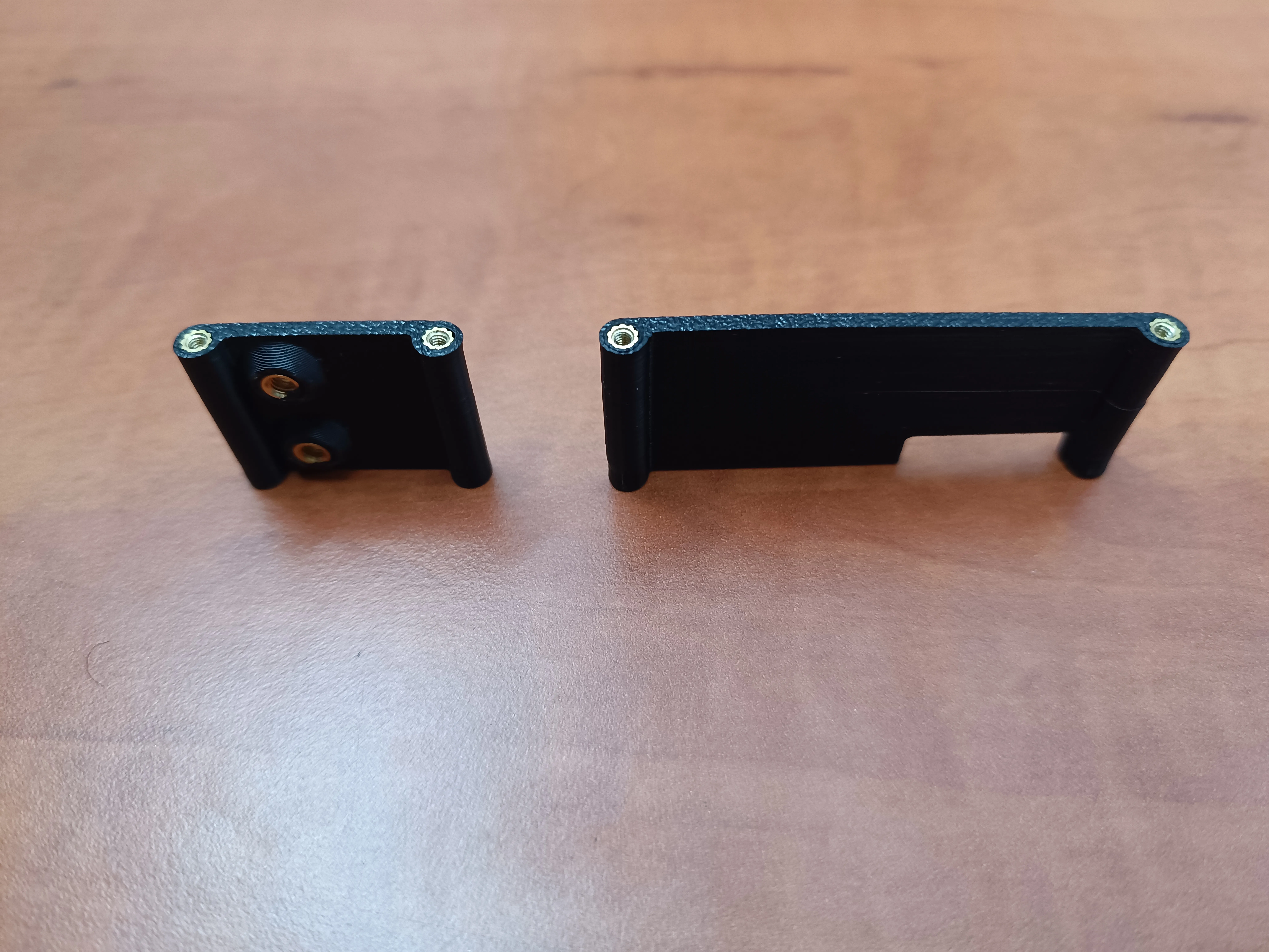
- Step 9: Using the 8 mm M2 screws, attach the top and bottom walls to the left wall.
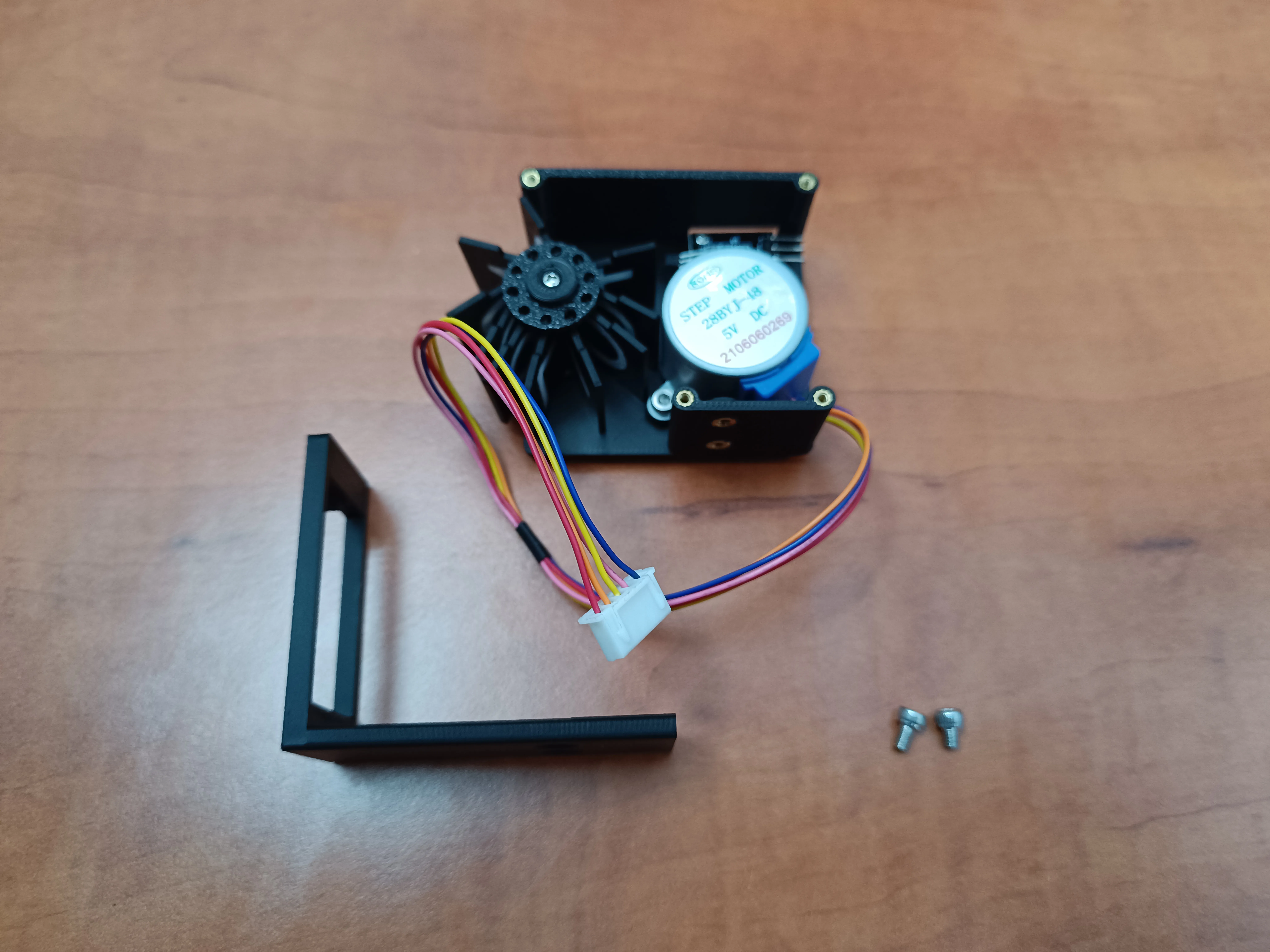
Step 10: Attach the outer case using the M3 screws.
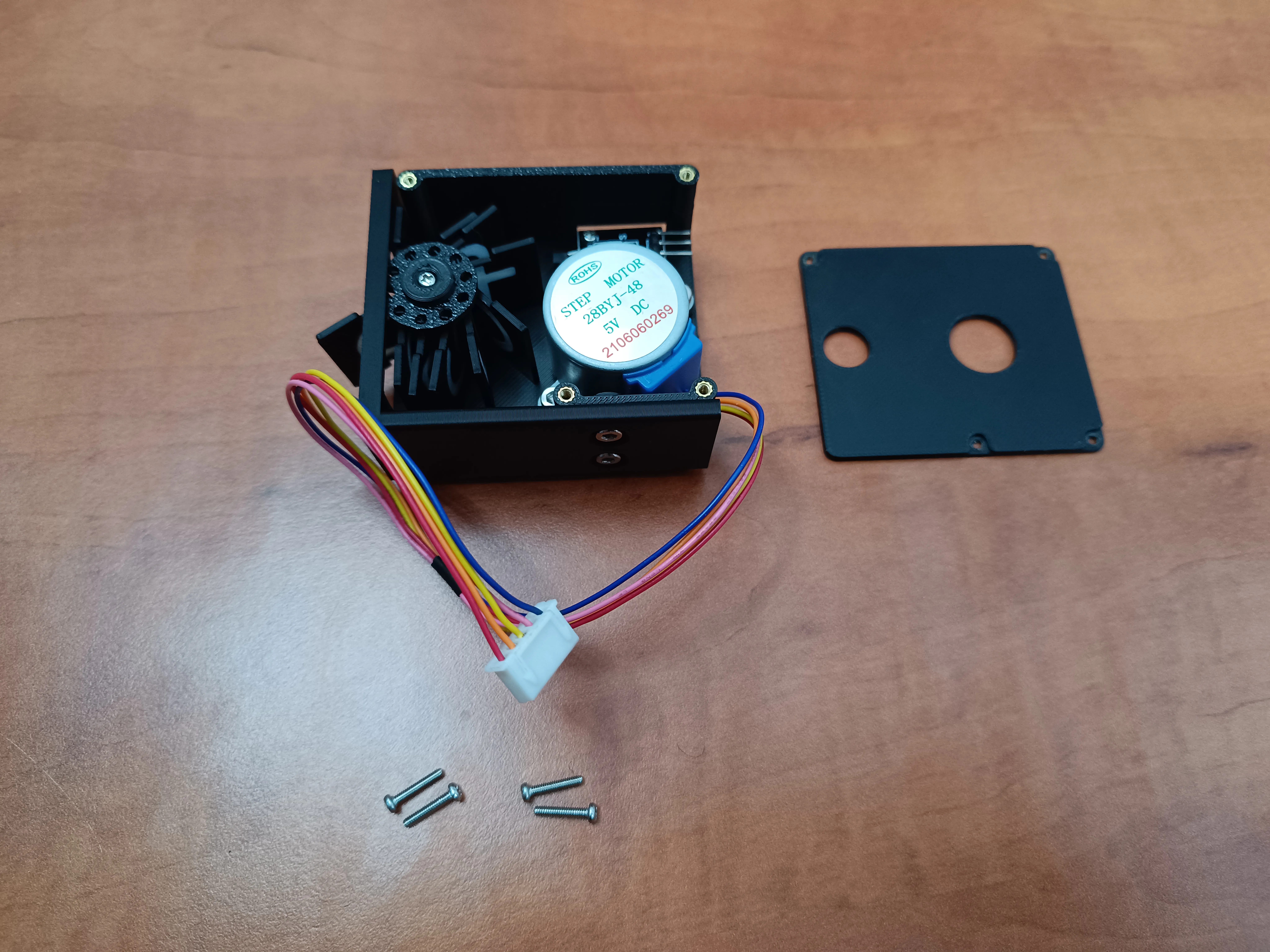
Step 11: Using the remaining M2 screws, attach the right wall to the assembly.
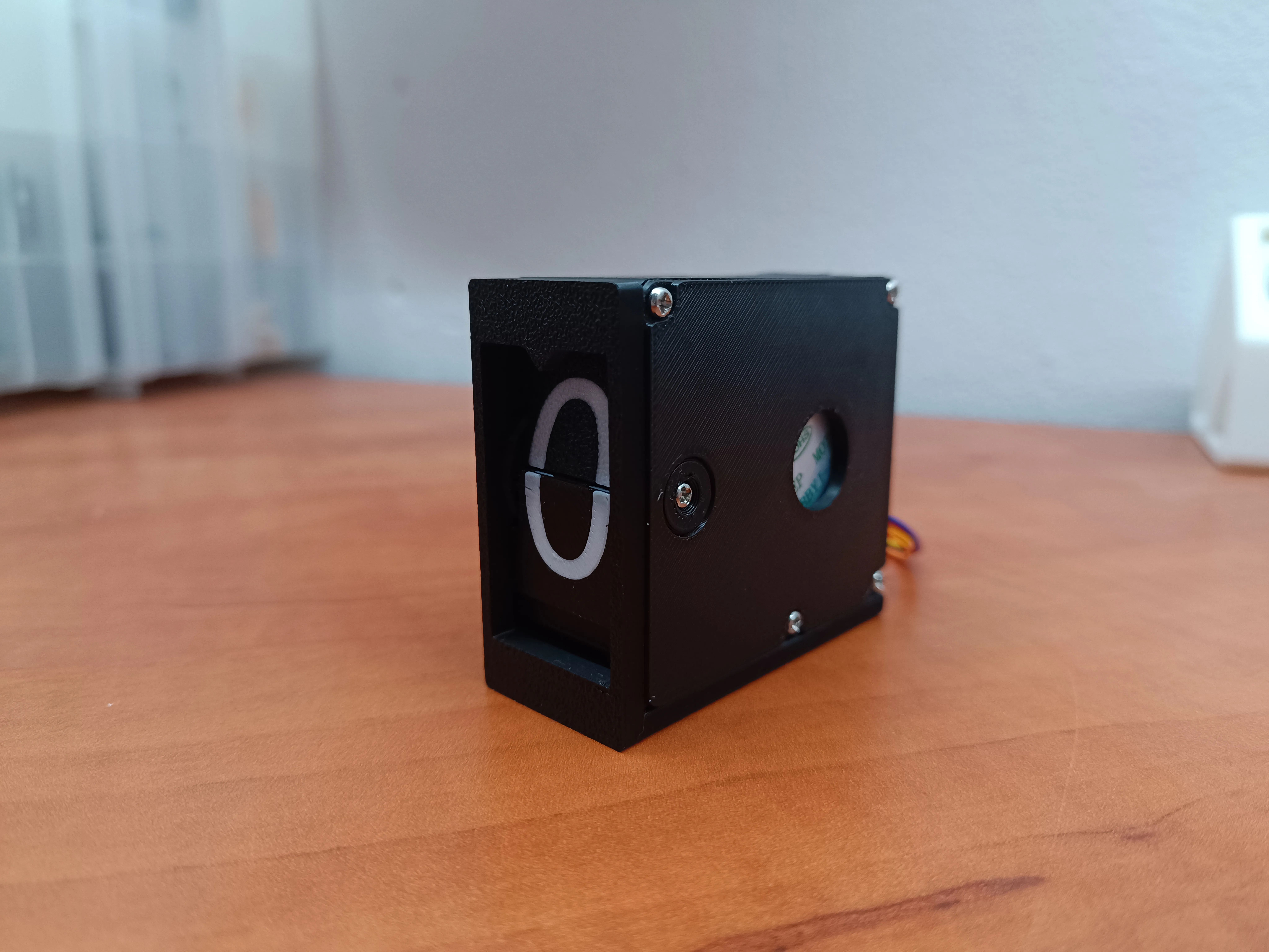
Ensure all components are securely in place and aligned properly.Congratulations! You’ve completed the assembly of the split-flap clock digit unit. It's now ready for testing and integration into your clock project.
License

You shall not share, sub-license, sell, rent, host, transfer, or distribute in any way the digital or 3D printed versions of this object, nor any other derivative work of this object in its digital or physical format (including - but not limited to - remixes of this object, and hosting on other digital platforms). The objects may not be used without permission in any way whatsoever in which you charge money, or collect fees.


Comment & Rating (13)