
Soldering fume extractor – USB-C (open source)


Print Profile(1)

Bill of Materials


Description
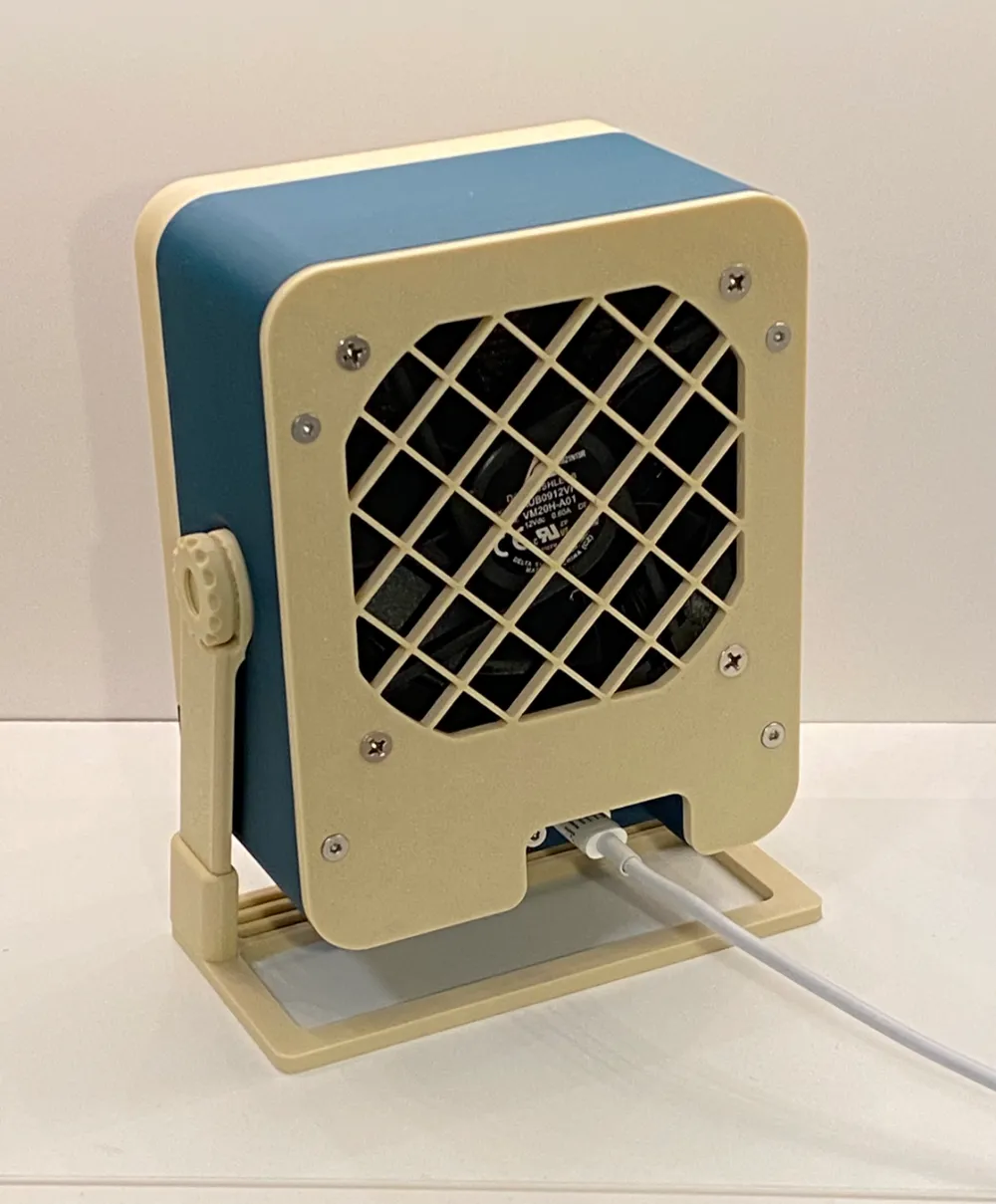
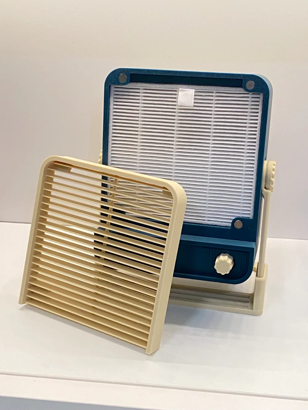
Compact soldering fume extractor built from readily available parts.
This design is open source:
Printing
Some of the parts are rather big so you want to avoid warping. Some tips:
- Clean your bed according to its usage instructions (e.g. dish soap for PEI)
- Use filament that shrinks less
- Consider using fire-retardant filament for PCB holders and main body, e.g. PETG V0 UL
The filament in photos is PLA+ by eSun and PLA+ by Elegoo.
Safety disclaimer
Note that the primary purpose of this device is to keep the smoke out of your face. While there is a filter, real fume extractors made for soldering in industrial/commercial environments are much bigger and more performant. Therefore, you still need to ensure you have good air circulation, and overall choose safety measures appropriate for the work you're doing.
Parts
| Part | Image | Note/Link |
|---|---|---|
| M3x10 flat head screws | ||
| M3 heat-set inserts | ||
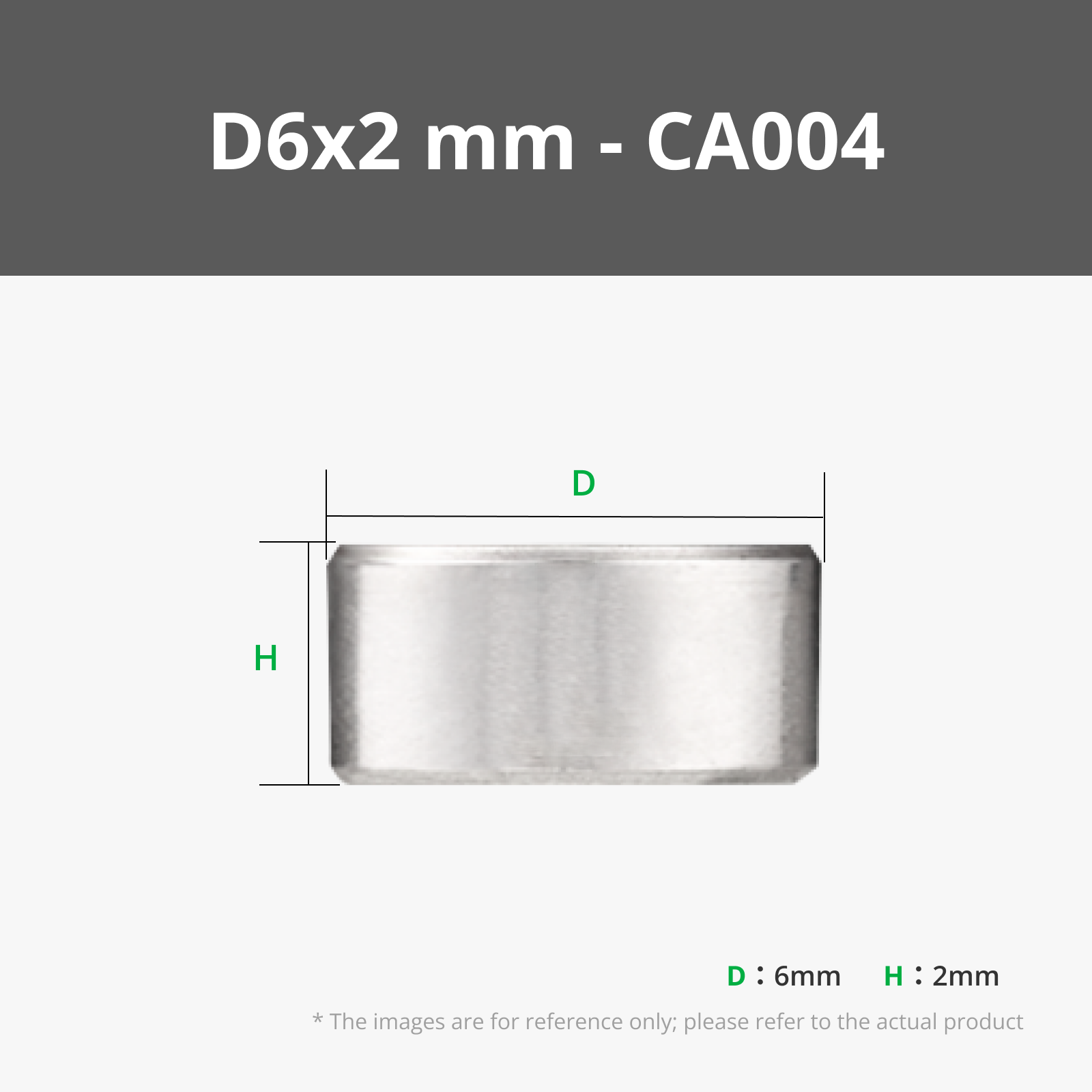
| Cylindrical magnet 6x2 | ||
| Fan | 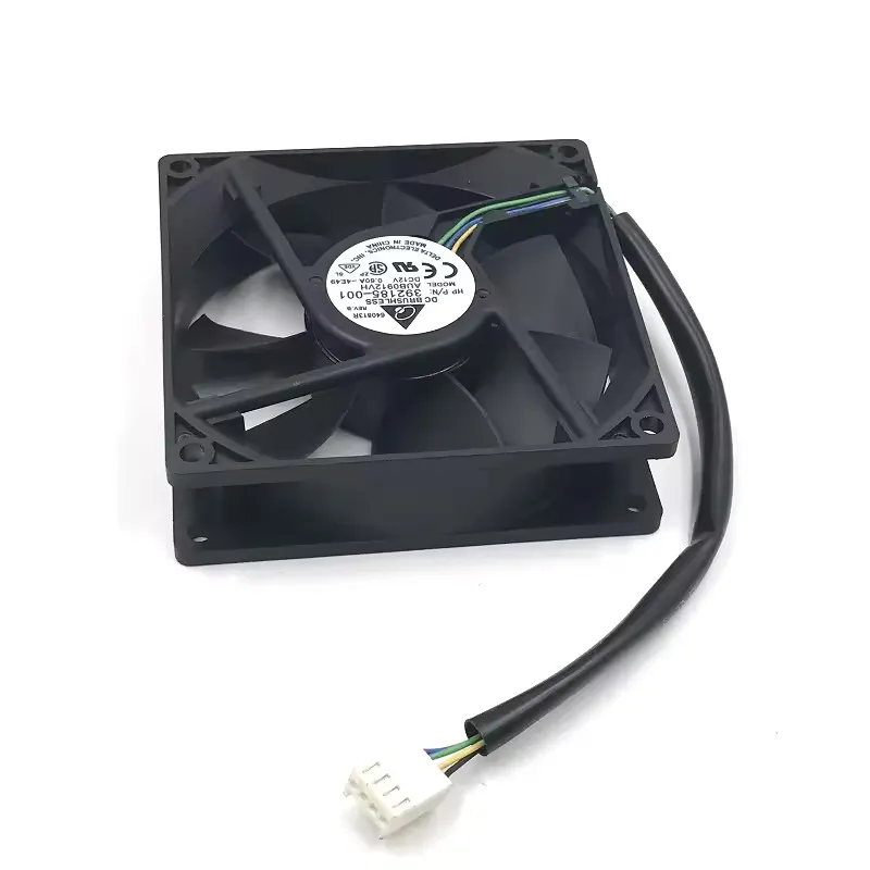 | Dimensions: 92x92x25mm Connector: 4-pin PWM
Keep in mind that some quiet PC fans will not be powerful enough to pull enough air through; so you can look for fans that have higher power, e.g.:
https://www.aliexpress.com/item/32821859212.html |
| USB-C adapter | 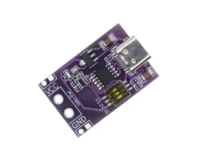 | Purple PCB with micro-DIP switch for voltage selection |
| Downconverter | 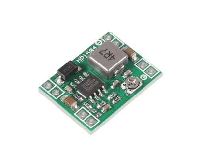 | Most USB-C PD chargers don't have 12V output, or only have it in PPS mode which the USB-C adapter doesn't support. So for simplicity, this design uses a downconverter. They come in fixed and adjustable versions. Either way, you want 12V output. https://www.aliexpress.com/item/1005005305772411.html |
| PWM controller | 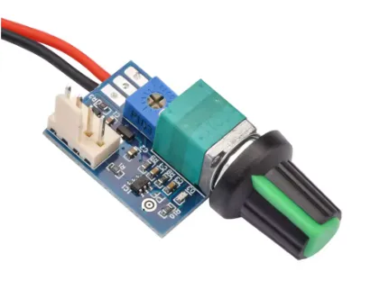 | 12V 4-pin PWM controller with off-switch
|
| Filter | 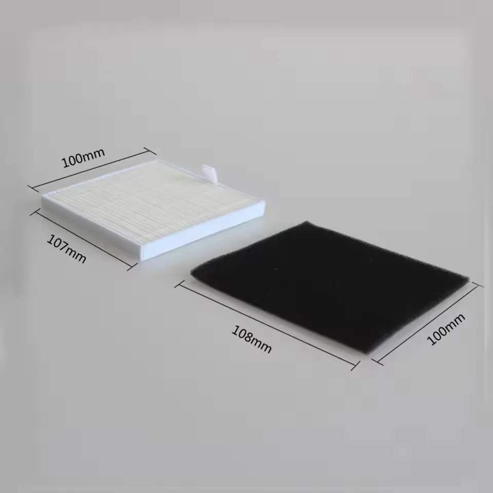 | https://www.aliexpress.com/item/1005005743698966.html |
Assembly
After printing all the parts/plates, follow the assembly sequence
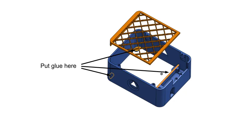
Glue in the inner filter grid
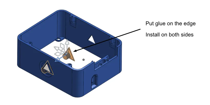
Glue in side screw inserts:
Install magnets on the front grille and main body. Ensure correct magnet polarity:
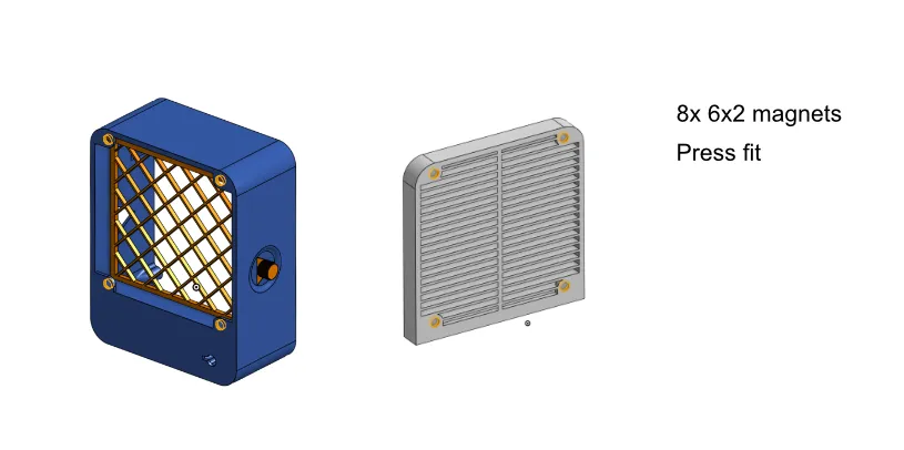
Install heat-set inserts:
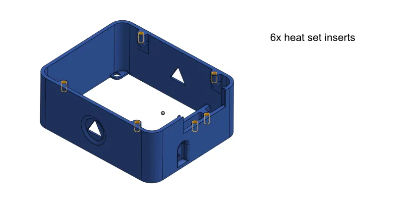
Put the PWM controller into its holder frame:
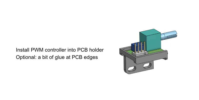
- Select 15V voltage on the USB-C board
Solder wires from USB-C board to the downconverter board:
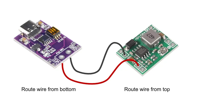
- If your downconverter is adjustable, connect USB-C and adjust the output voltage of the converter to 12V
Solder wires from downconverter to PWM controller
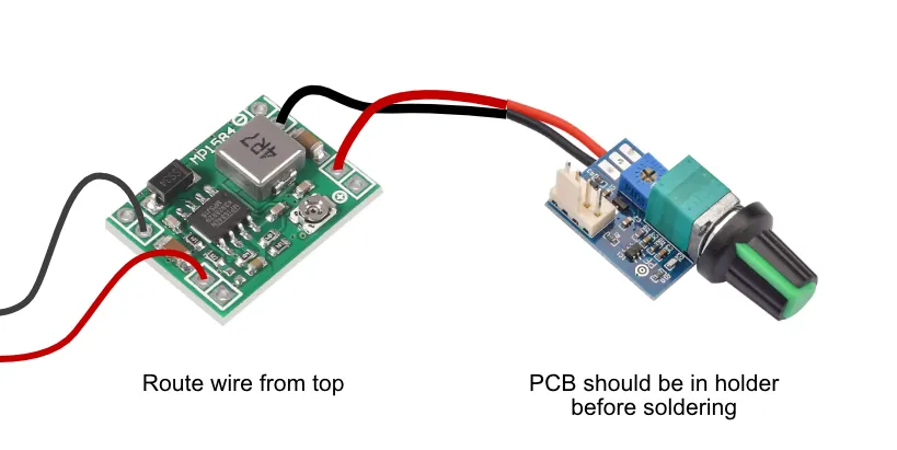
- Install the PWM controller together with PCB frame into the main body. Lightly tighten the nut on the potentiometer
- Screw in 2 M3 screws from the bottom to fix the PCB frame of the PWM controller. You don't need to tighten it a lot, it's just there to restrict movement of the frame.
- Tighten the potentiometer nut more. Put the PWM controller potentiometer handle on the front of the device. Use glue if necessary to fix.
Put the USB-C PCB into a holder frame. You can use a drop of glue to fix its position:
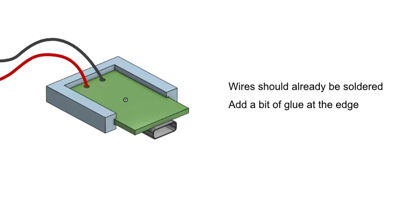
- Put the USB-C PCB together with holder into the main body. The USB-C connector should be on the bottom side of the PCB. You don't need to glue it in.
- Slide in the bottom case part. Position the USB-C board so that the connector slips into the hole in the case.
- Screw in two M3 screws to fix the bottom case part.
- Attach the fan to the back cover (make sure it's pulling the air) using screws provided with fan.
- Connect the fan to the PWM controller. It might be a bit tight, but you can work out an angle; I tried 3 fans from different manufacturers and it was possible to connect.
- Route the fan cable and close the back lid.
- Screw in 4 M3 screws to keep the back lid in place.
- Install the filter in the front: carbon filter goes on the grid first, then particle filter on top.
- Assemble the stand: slide in left and right legs fully into the respective slots.
- Attach the stand to the filter and screw on the side nuts.
- Carefully glue on the bottom decorative chin.
- Finally, snap on the front decorative grille.
License



Comment & Rating (49)