
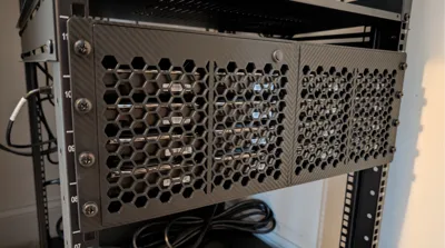
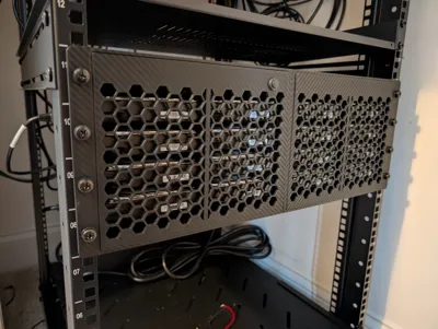
16 Drive 4U Rack Mounted Hard Drive Enclosure
Print Profile(2)


Bill of Materials



- SAS_Converter x 2: https://a.co/d/hykCaCl
- SFF-8643_SATA_Breakout x 4: https://a.co/d/bsuH4Rq
- SFF-8644_Cable x 4: https://a.co/d/iA4uFIA
- HBA_Card_SFF-8644_External x 1: PCI_External_HBA_Card
- 3x2_Magnet x 72: https://a.co/d/9Bln771
- SATA_Power_Cable x 4: https://a.co/d/6rhuS62
- SATA_Adapter_Ali x 16: https://www.aliexpress.us/item/3256807274888200.html?spm=a2g0o.order_list.order_list_main.5.55bb1802NMQI0F&gatewayAdapt=glo2usa
- SATA_Adapter_Amazon x 16: https://a.co/d/9AtQ5jb
- Nylon_Standoff x 4: https://a.co/d/geekkmT
- Latching_Switch x 1: https://a.co/d/0iaCNxa
- 120mm_Fan x 3: https://a.co/d/6yht3WV
- 92mm_Fan x 2: https://a.co/d/9oTVfEr
- Extended_Rack_Screws x 1: https://a.co/d/8enfdzr
- 90_degree_PSU_Power_Cable x 1: https://a.co/d/f5X65GZ
Description
Please comment, rate, and post a make!
Be sure to check out my other models!
PLEASE READ EVERYTHING BELOW BEFORE STARTING THIS PROJECT!
Please comment, rate, and post a make!
Be sure to check out my other models!
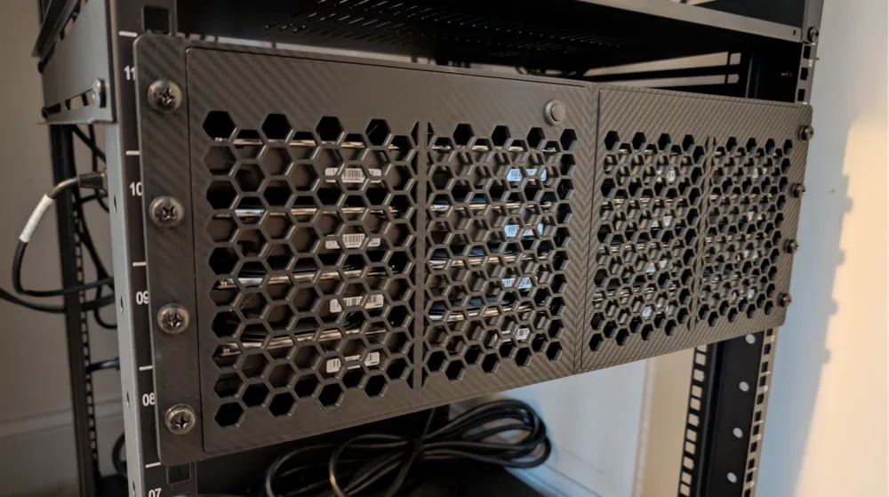
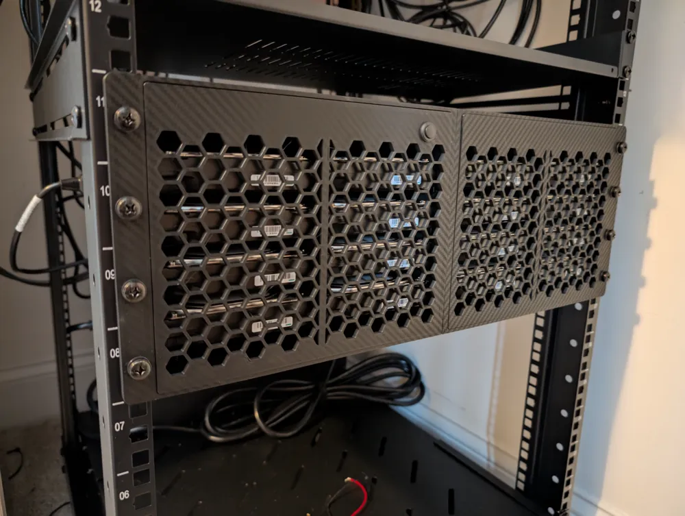
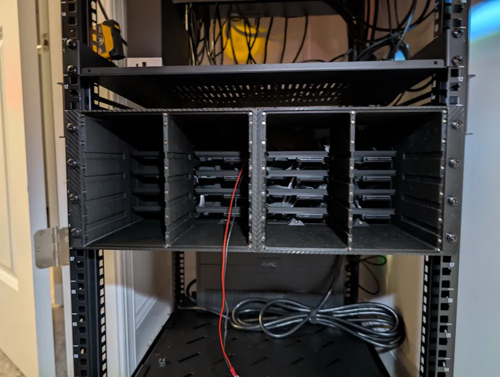
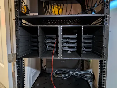
This is my take on a rack mounted, 16 bay, 4U JBOD/HBA drive enclosure. This is a medium-level difficulty project and assumes some basic knowledge of PC components/assembly. This is a true HBA with no computing and will require a PC with an HBA card (like the LSI 9206-16E) to access the drives.
DISCLAIMER:
You build this assuming all risk. I have little concerns over the strength of this model, but there are a huge number of factors that go into how strong a 3D print is (e.g., layer adhesion, filament type, filament quality, whether or not Mars is drinking Gatorade). Additionally, most filament is non-conductive. This does lead to the chance that static charge can build inside the enclosure and a discharge event (e.g., you grab a drive with your bare, chicken grease coated fingers) could fry something. I've been running a 3D printed drive enclosure of some form for the better part of two years with no issues. Most of the components are grounded providing some protection, but proper ESD practices should always be followed.
FEATURES:
- Using the SATA adapters, the drives are easy swap (this is different from hot swap).
- The enclosure should be powered down before swapping a drive.
- Plenty of cooling
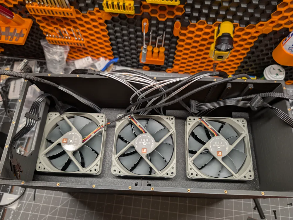
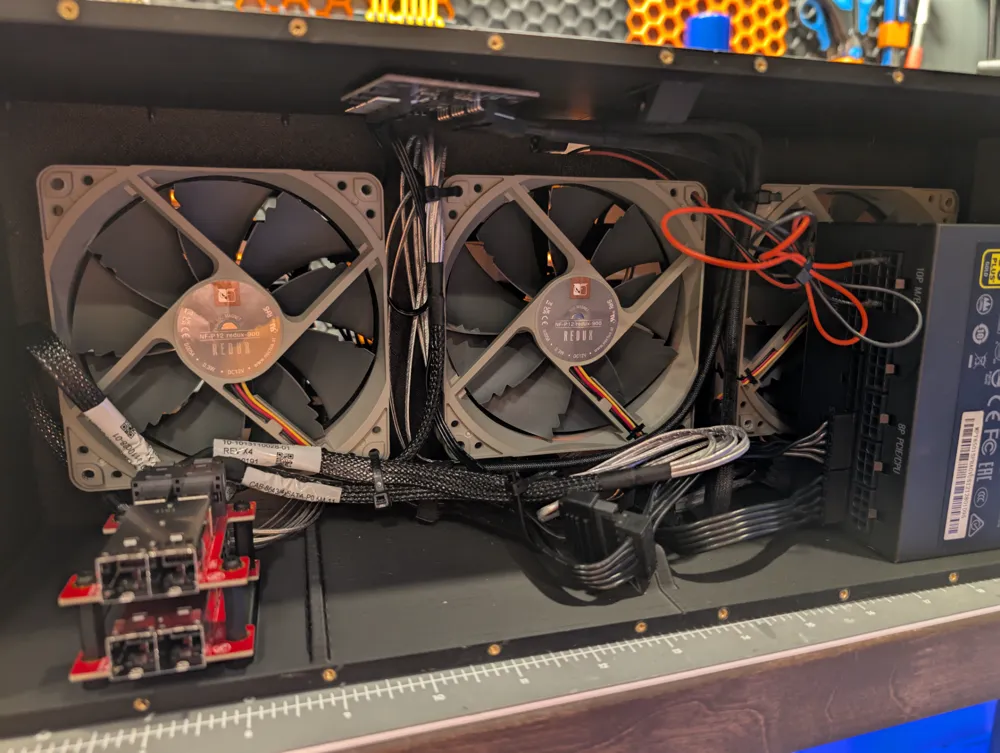
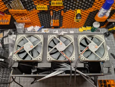
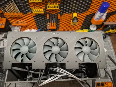
- Three 120mm fans directly behind the drives pull cool air across the drives from the front.
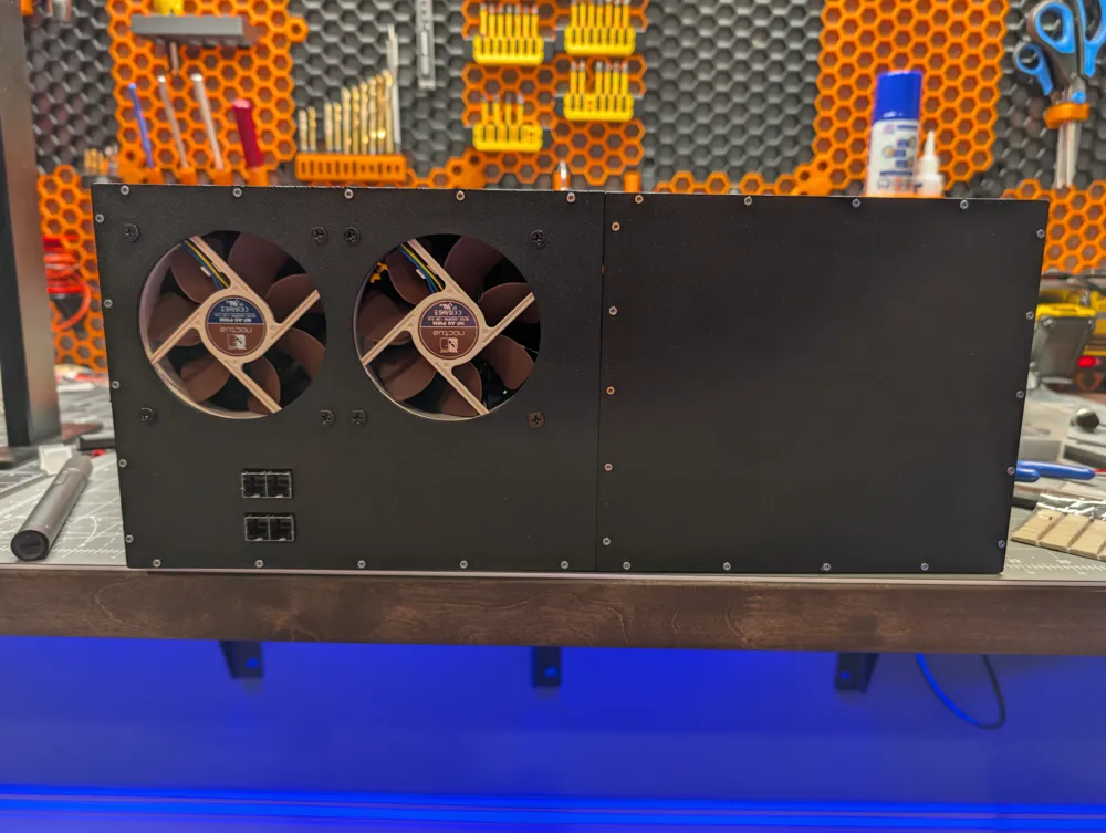
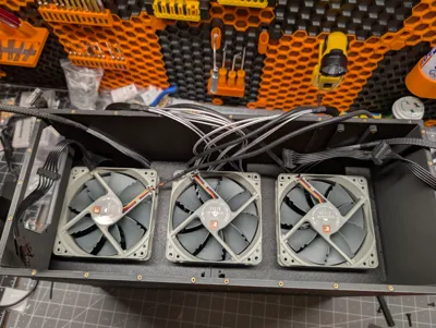
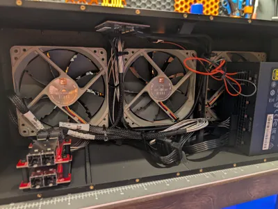
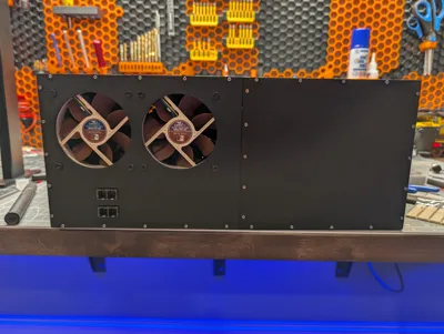
- Two 92mm fans in the back, along with the PSU fan, exhaust the heat out.
- Can use an ATX or SFX PSU
General Items Before Starting the Project:
- I'd recommend using a fully modular PSU to help with cable management.
- Be sure to account for power requirements:
- I have Seagate IronWolf Pro drives. Per their spec sheet, they pull ~2 amps at startup with ~0.6 amps average during operation per drive. Both the SATA power adapter cables and the PSU cables that I'm using have 18 gauge wiring so a single SATA connector on the PSU can handle about 20 amps. I have two power connectors off the PSU with each one running eight of the 16 drives to keep the load under 20 amps. The PSU I'm using has a single, 70 amp 12V rail that is more than capable of powering all the drives.
- Determine how you're going to switch power.
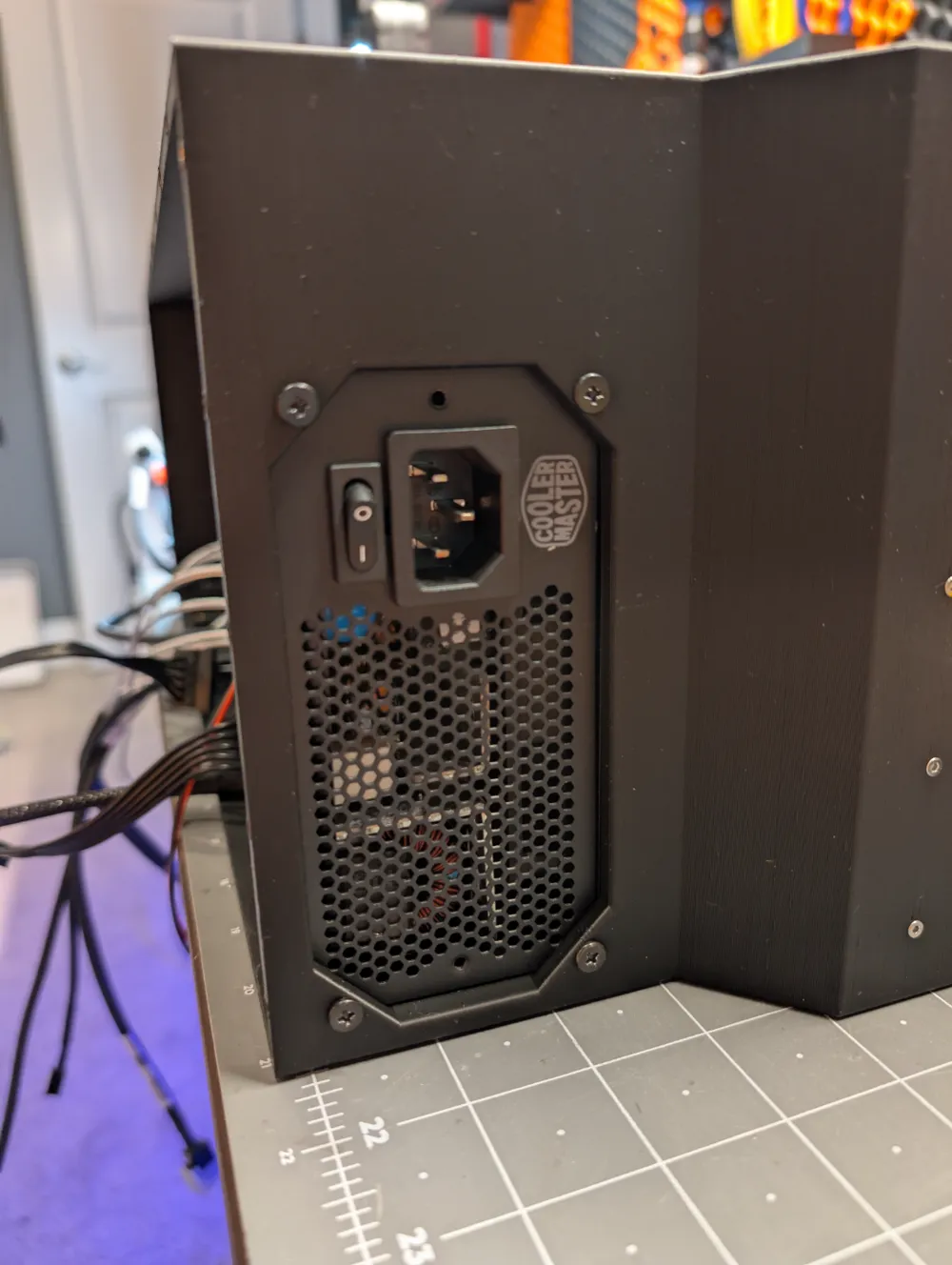
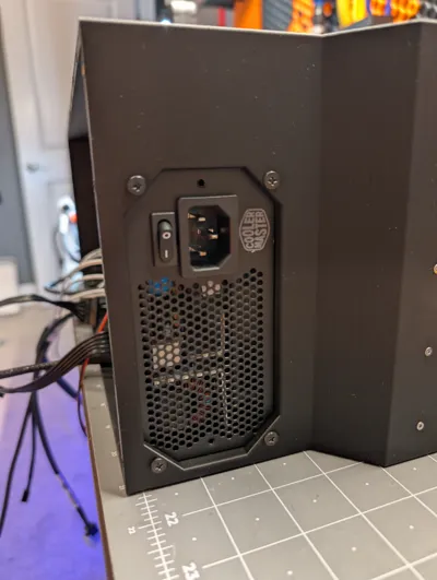
- You can opt to use the power switch on the PSU, a smart plug, and latching switch, or something else; but you'll want to have this figured out ahead of time to make sure you have a cutout if needed.
- I opted to use a switch going directly to the PS_ON pin and ground on the PSU motherboard connector. This way, I don't have to use the main cable. There are a litany of “how to” out there covering this.
- Determine how you're going to power the fans.
- I had a generic fan hub sitting around that's powered from SATA and just used Gorilla putty to mount it to the roof of the enclosure.
- Here's one from Arctic.
- You could opt for splitters and a conversion cable to power them directly off the PSU.
- You could use a PWM controlled hub.
- I had a generic fan hub sitting around that's powered from SATA and just used Gorilla putty to mount it to the roof of the enclosure.
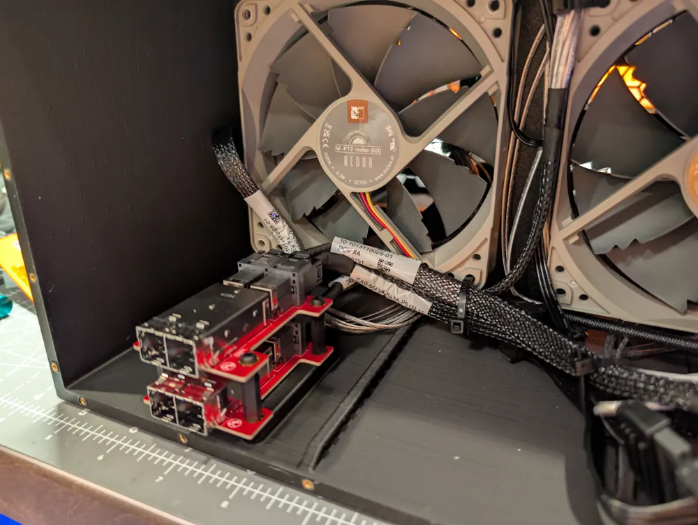
- The mounts for the converter cards in the enclosure are specifically spec'd for the one linked in the BOM. Another brand may not work.
- Since this is plastic, the mounting ears are thicker than most rack mounted items. I've provided a link to longer rack screws for mounting. The ears are 6mm thick and you'll want plenty of thread engagement.
PRINTING:
General Tips:
- Be sure you have enough filament on hand before starting.
- Wash your build plate(s).
- I give mine a light scrub with regular Dawn dish soap before starting the project and an IPA wipe down in between prints.
- Using the gold, textured Bambu PEI plate, I didn't need a brim for any parts, but YMMV.
- Have a print plan.
- I would recommend printing the larger pieces where you will be able to monitor the prints. These are large parts that can warp and peel from the build plate. Nothing is worse than having a 17 hour print finish just to be greeted by a potato'd corner.
- I printed two of these in an X1 with the door shut, lid on, and AUX fan set to 40%. I do have a vented riser. The biggest thing is to make sure there are minimal drafts around the print.
- FOR THE BUTTON: I used a negative part in Bambu Studio for the button cutout. This can be resized, replaced, or removed to fit your needs.
- FOR THE DRIVE RAILS: I have added a print profile to print the rails with TPU. This will help with vibration resonance between the drives. Up to you whether you want to print in standard filament or not.
Print Settings:
If you're not using my print profile, here is what I used:
For everything except the main body parts:
- 4 walls, 5 top layers, 5 bottom layers, 15% gyroid infill, aligned seams
Main Body Parts:
- All parts:
- 4 walls, 5 top layers, 5 bottom layers, 15% gyroid infill, random seams, outer/inner wall sequence
- Front parts:
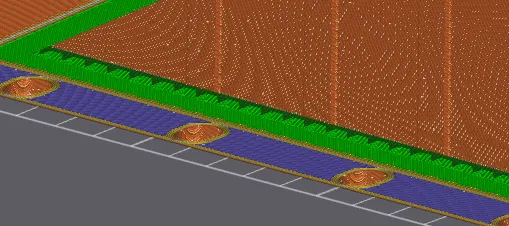
- Face down on the plate
- Standard supports where the face is inset:
- Back parts:
- You'll want the front facing side on the plate
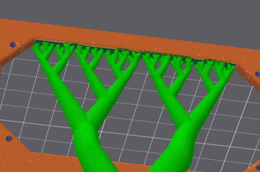
- For the PSU cutout, paint the top edge and use tree supports on the build plate
DRIVE RAILS:
The print profile for the drive rails can be used regardless of what filament you want to use, but may need adjusting if you use something besides TPU (you can just use the drive rails in the main profile). The profile, as uploaded, works for me printing with Overture TPU. The filament profile has an increased retraction length to get rid of stringing between the pins.
This model was made directly in Bambu Studio using primitives and modifiers allowing for easy adjustment. The Overture TPU I'm using had sizeable shrinkage on the X and Y axis so I had to make everything slightly oversized (2.85mm diameter pegs in the model got me 2.68mm in the actual print)
If you need to adjust, just flip to the “Objects” tab.
The “Generic-Cylinders” are the pegs. If you need to change the diameter, change both the X and Y values.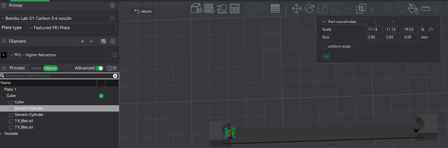
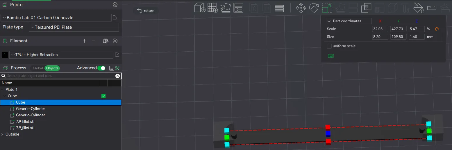
The “Cube” is the main bar.
ASSEMBLY:
Before doing anything, make sure your components are all working. I'll provide more information below about my particular setup, but you want to make sure your fans, adapters, converters, and cables are all functional before putting this together. This is good general advice for an PC-style build.
HARDWARE FOR ASSEMBLY:
I've listed the needed hardware in the BOM (along with links to purchase) but will reiterate:
| Type | Size | Quantity | Purpose |
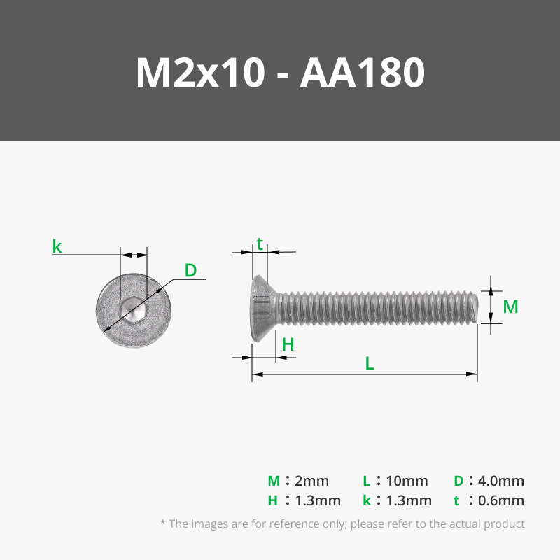
| Flat head screw | M2 x 10 | 30 | Fan frame |
| Socket head screw | M2 x 8 | 51 | Back panels / SATA adapter bar |
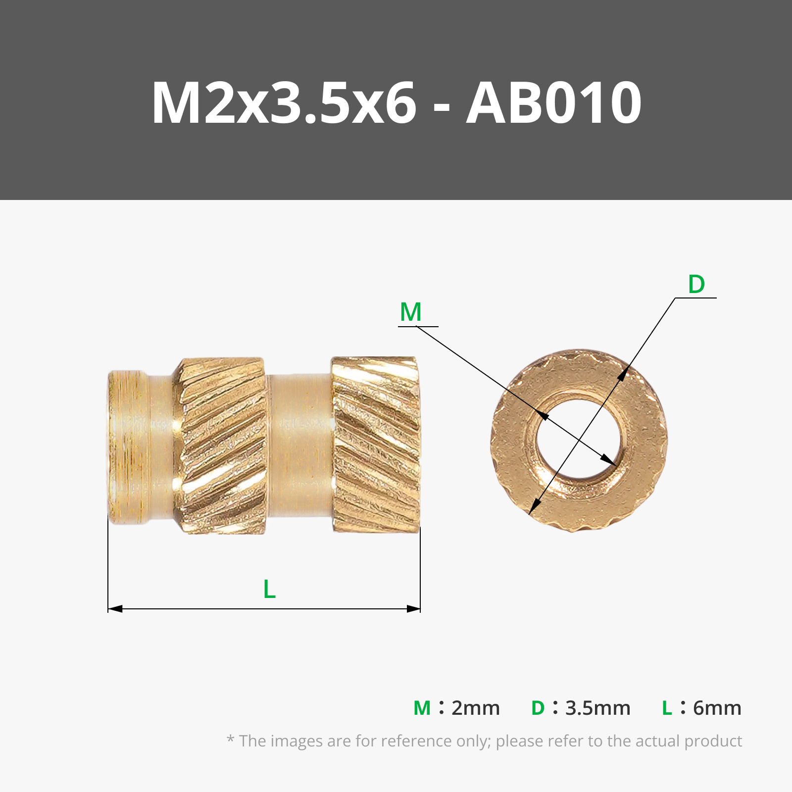
| Heated insert | M2 x 6 | 91 | Fan frame / back panels / SATA adapter bar |
| Button head screw | M4 x 10 | 21 | Joining the four body pieces |
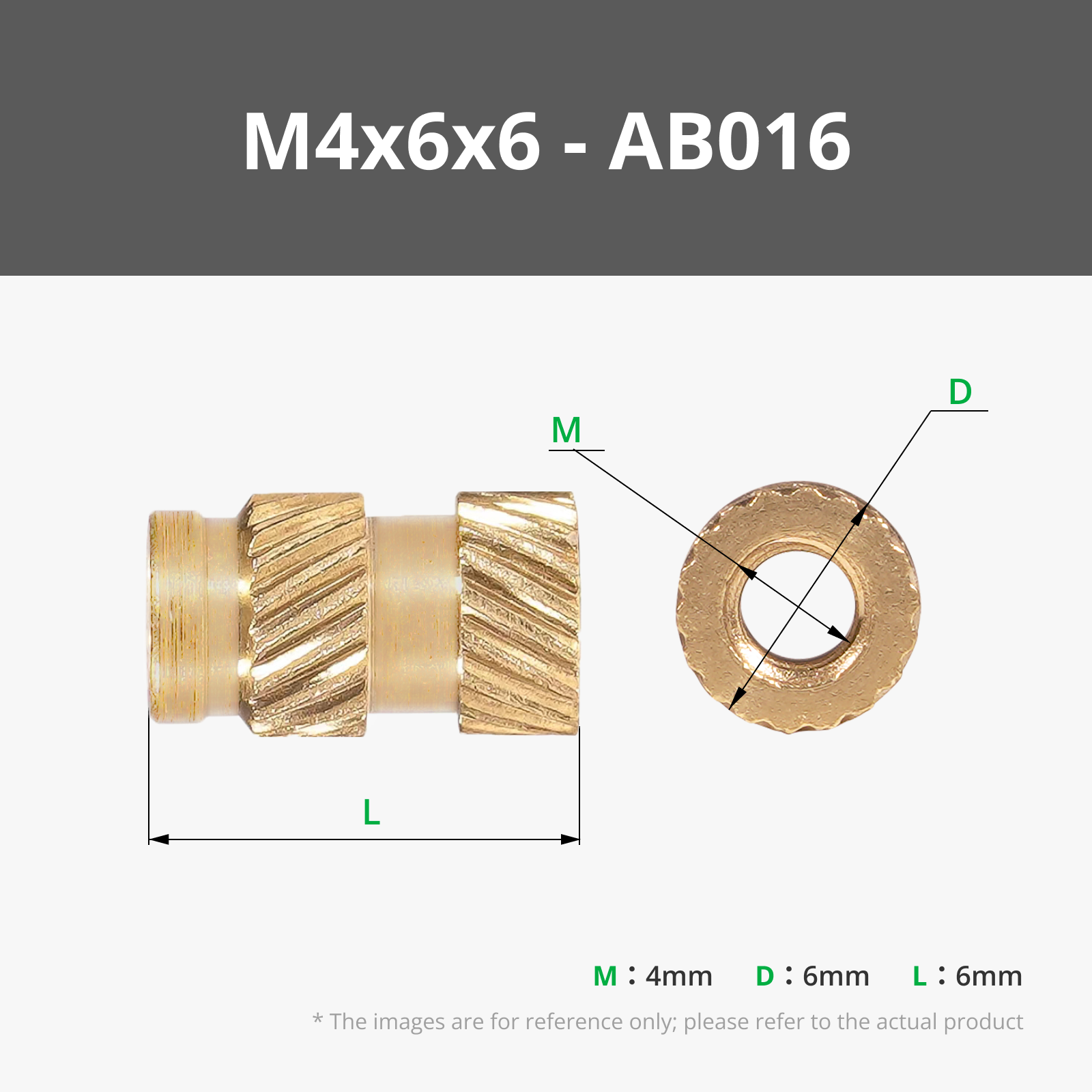
| Heated insert | M4 x 6 | 21 | Joining the four body pieces |
| Heated insert | M3 x 6 | 4 | Mounting the SFF-8644 to SFF-8643 converter card |
| Nylon standoff | M3 x 20 | 4 | Mounting the SFF-8644 to SFF-8643 converter card |
| Nylon screw | M3 x 6 | 4 | Mounting the SFF-8644 to SFF-8643 converter card |
| Socket head screw | M3 x 12 | 32 | Mount the SATA adapter to the bar |
Add the heated inserts:
I started by adding all of the heated inserts first. The side for the heated inserts will be the one with the larger hole.
- Outside edge of the fan frame (M2)
- The mid seam of the front right piece (M4)
- The back edges (M2)
- The tabs for joining the back panels together (M2)
- The tabs may soften and bend. I just made sure they were on a flat surface with the rest of the panel supported to keep them from moving too much.
- The interior tabs (M4)
- The back edges between the drive slots (M2)
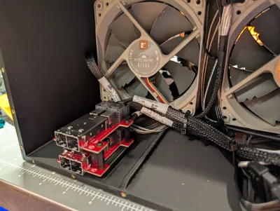
- The mounting points for the converter cards in the back right piece (M3)
- For these, I just used a large, flat soldering iron tip to push them in.
Add the magnets:
The magnets for the front panels are intended to be press fit. Make sure you keep track of the polarity. I use this handy tool (one for each polarity). You may need to cleanup around the holes depending on how well the supports break off.
Join the front body pieces together:
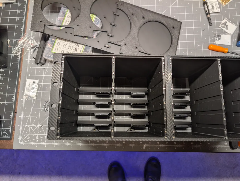
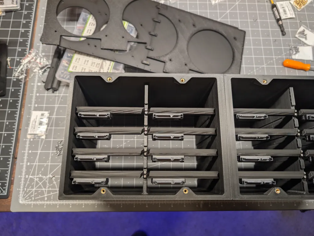
The front pieces get nine M4 screws to join them together. The back screw holes are blocked after adding the SATA adapters in the next step, so be sure to do this first.
Prepare the drive slots:
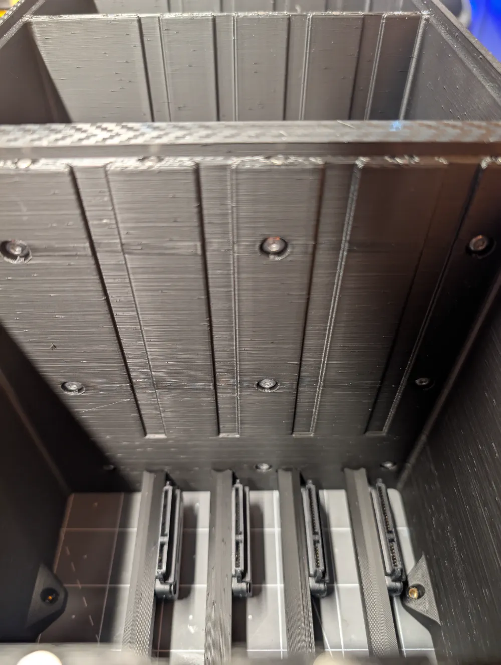
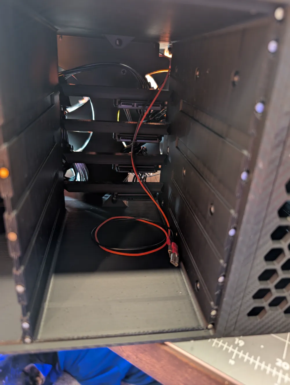
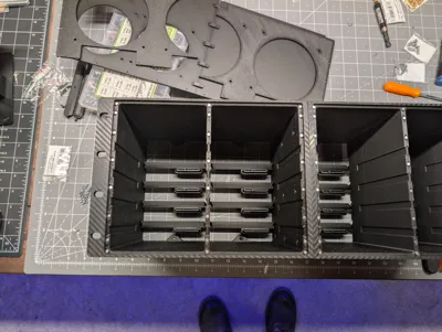
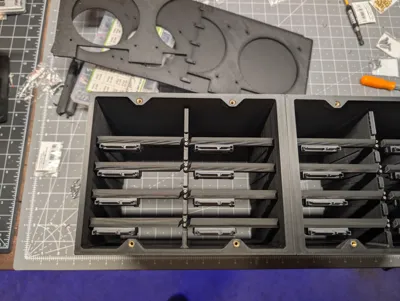
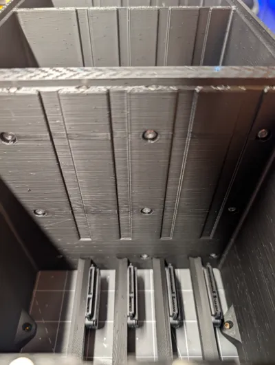
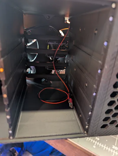
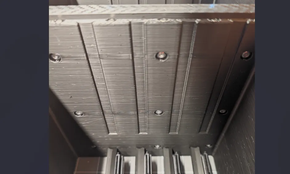
The bars for the SATA adapters are designed to slot into a mortise (cutout) in the main body on one side and the other will get screwed into the back side of the divider. The brackets have a letter D embossed. This should be pointed up and towards the drive bay. You'll screw the adapter in with the female side on the same side as the letter. This takes two M3 screws.
A note on the adapters:
I've provided links to both US Amazon and AliExpress. I bought both and, from what I can tell, they are identical; however, you can get 10 from AliExpress for the same price as two from Amazon. I did have a few of the ones from Ali where the outside tabs broke (you can see in the picture below) but I blame this on shipping vice the item (they were all just tossed in a plastic bag).
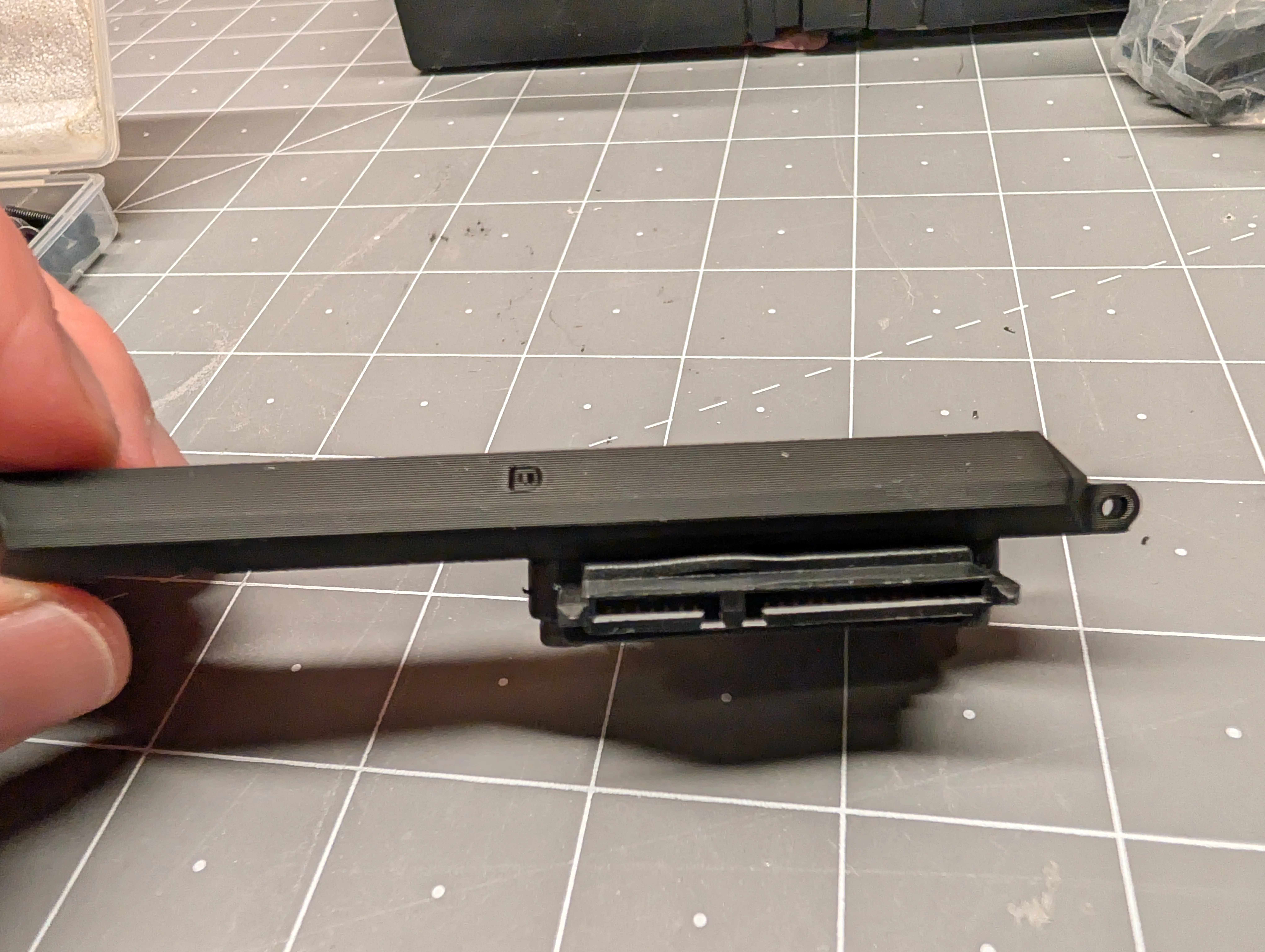
Once you have the adapters mounted, slot the tab (tenon) into the slot in the body and screw the other side in.
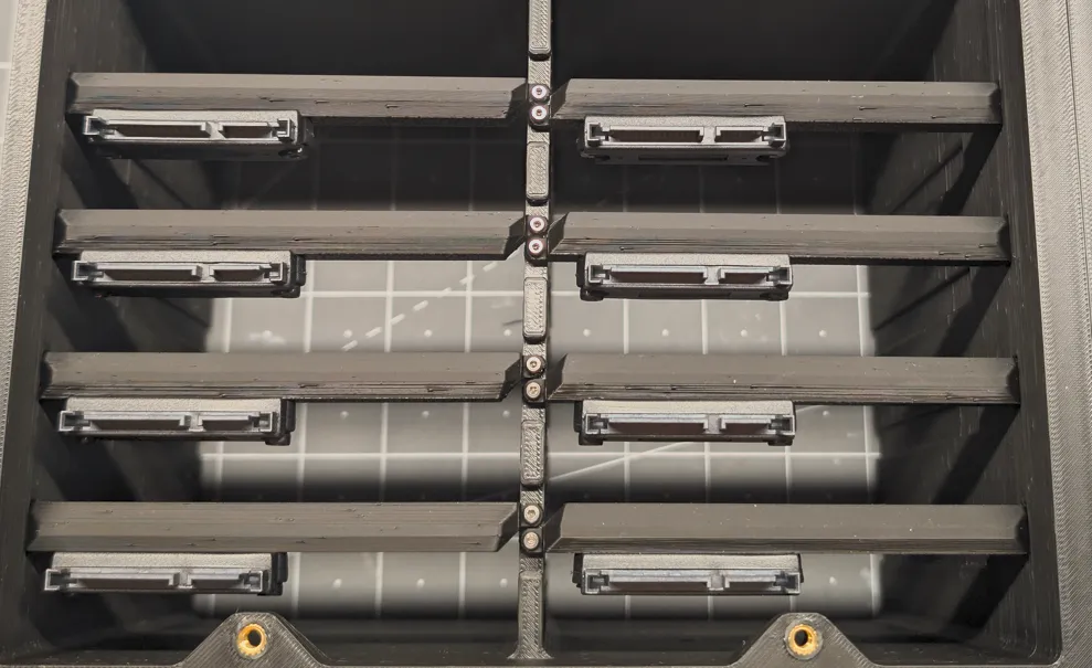
Join the rest of the body:
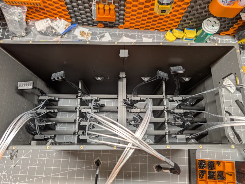
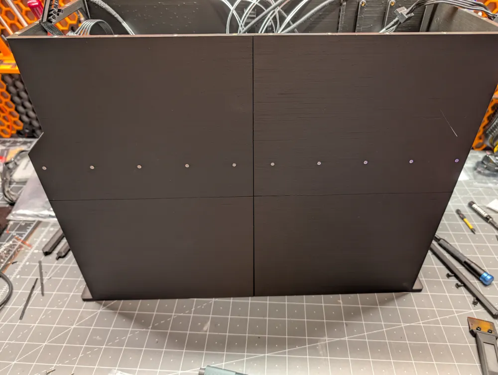
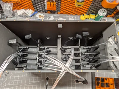
The back halves get M4 screws between them and then M4 screws to connect them to front half. At this point, you can go ahead and wire up the data and power connectors for the converters along with zip-typing them in place. I opted to tighten the zip ties enough to hold the cables where I wanted them but loose enough that I could still pull the slack out if needed with a little force.
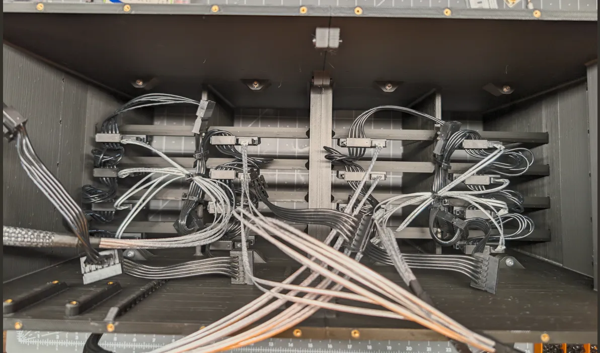
If opting to use a front mounted switch, now is the time to run the wires from the front out the back.
Mid-fan frame:
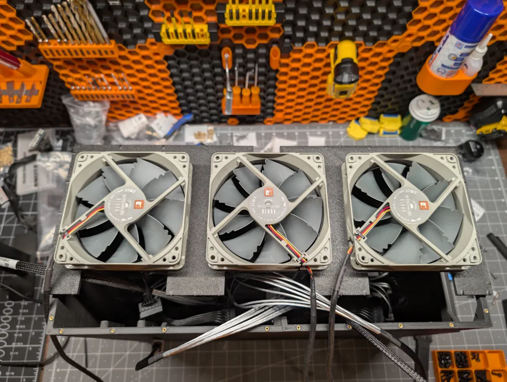
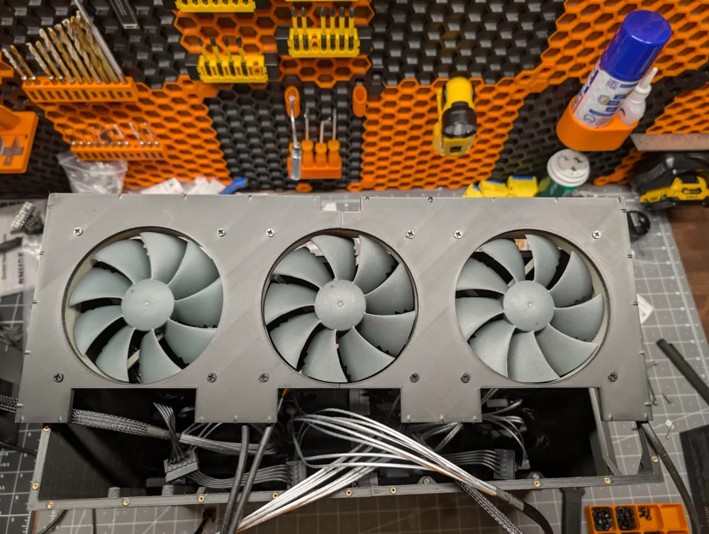
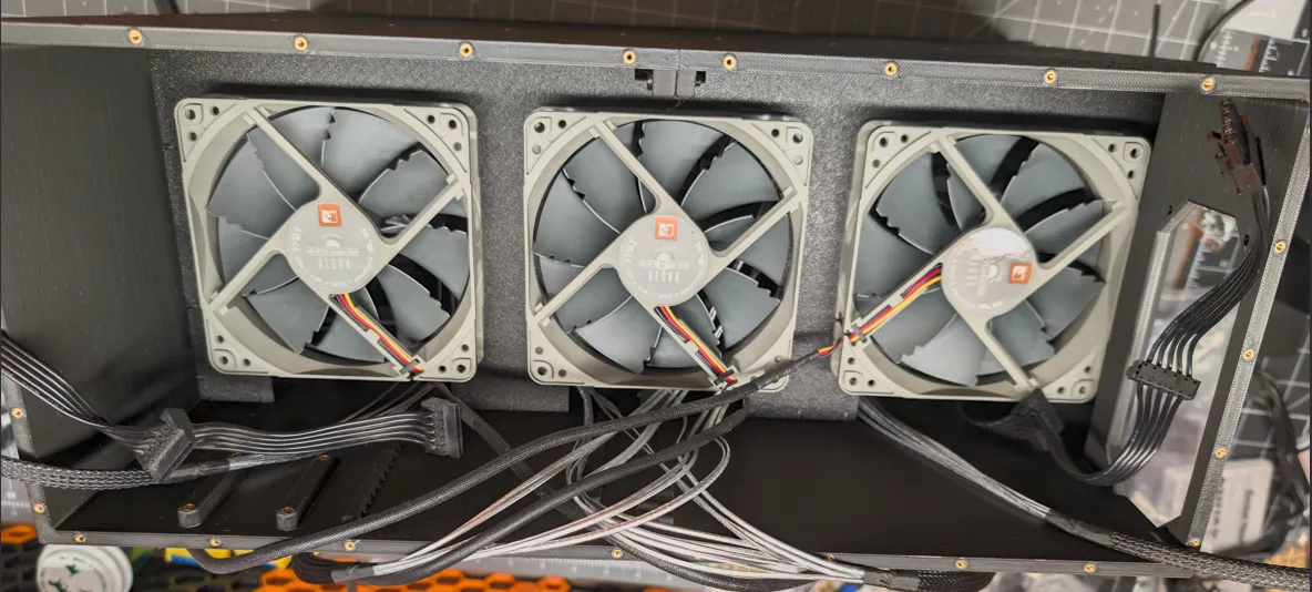
Add the middle fan to the frame. This will align and join the two halves into a single piece. Make sure you double-check your fan direction and think about where the wires need to go. Insert the frame into the body. This part is a bit tricky as the tolerances are pretty tight and you'll want to make sure your data and power cables are passed through the slots. But, with enough finagling, it's doable.
Once in place, add the flat head M2 screws from the outside into the threaded inserts.

PSU and converter cards:
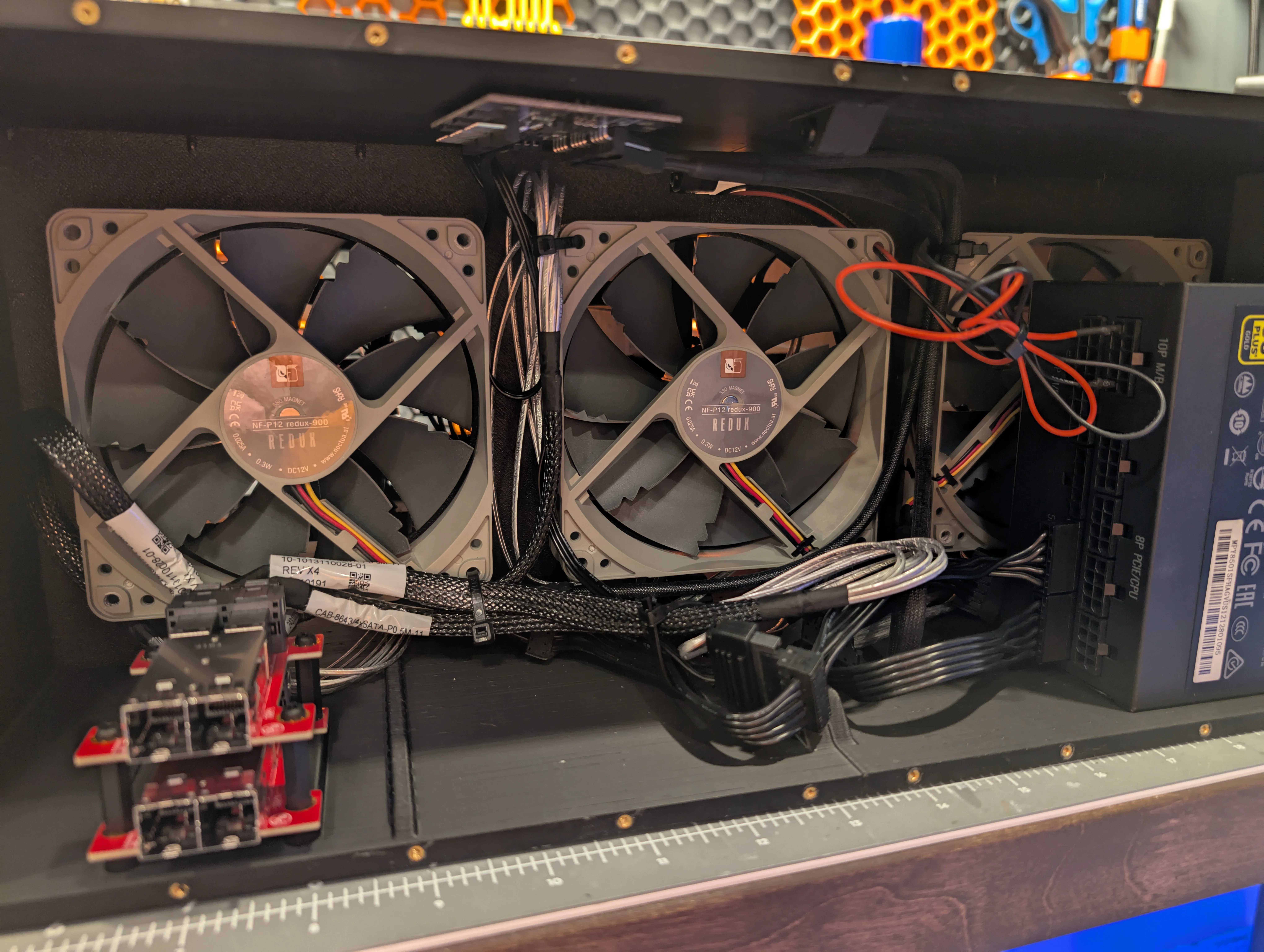
Install the converter cards. The bottom one gets places directly on the little sleds with 20mm long standoffs holding it down. Plot the second card on top and add screws to secure them in place. Install the PSU and get everything cabled up that is already in place. This is also a good time to tidy up the cables using the zip ties mounting points. You'll see here that I'm using a random fan splitter that is powered over SATA I had laying around. There are a number of options to get the fans powered including using a PWM controller if you want to control fan speed.
Back Panel:
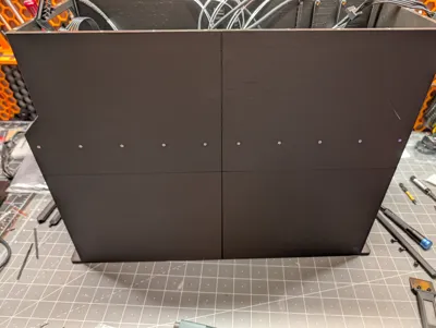
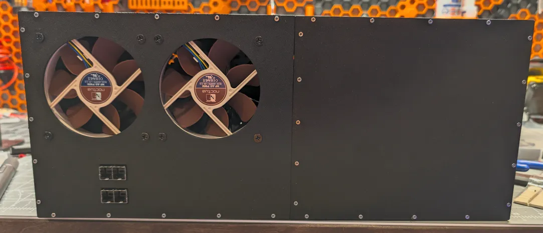
Screw the panels together using M2 screws in the mounting tabs. Add the two fans double-checking the orientation and thinking about cable direction. Connect the fans up and place the panels on the back. Add the M2 screws along the entire perimeter to lock it into place.
Prepare the drives:
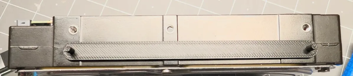
Pretty simple. The drive rails have pegs that go into the front and back screw holes on the sides. Just be gentle while inserting.
Mount the case:
At this point, the case is ready to be mounted in the rack. Nothing special here. The holes are setup to use the middle screw position for each unit. The setback for the PSU should be enough to bend the power cable if you have an enclosed rack. The best bet is to use a 90 degree power cable like this one.
(Optional) Button Wiring:
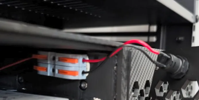
I used some straight-through wire nuts to allow me to disconnect the button if needed. I just mounted the connectors to the wall using Gorilla putty.
Install the drives:
Again, straightforward. Line the rails up with the slots in the enclosure and push them into place. You should feel them seat into the connectors.
License



Comment & Rating (47)