Inline 2 Vacuum Engine


Print Profile(2)

Bill of Materials

Description
After many months of developing, it’s finally here!
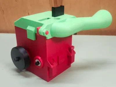
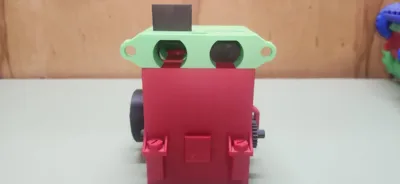
This is an Inline 2 Vacuum Engine, a model of an inline 2 internal combustion engine, that runs off a vacuum. I have spent months working out every little detail and mainly trying to get every tolerance perfect. I also go through a lot of work on all of my models to ensure that they are easy to print, and with minimal supports.
This model is completely press-fit, no glue, no tape, no magnets, just plain old PLA, modeled with the intent of being easy and fun to assemble and mess with, for experts to beginners to people who just enjoy messing around with cool contraptions. Additionally, those who have previous experience with vacuum engines can attempt to performance tune it, by changing the offset the camshaft has on the crankshaft.
Simply print out all the parts (don't forget to boost with that free boost token ;), assemble with the easy assembly instructions, and enjoy!
Note: You will need six 608 bearings, either 3D printed versions from Makerworld, or the metal versions which I have included in the Bill of Materials from Makersupply. Also note that the tolerances are very good for a Bambu Lab A1, but I cannot guarantee perfect fits with other printers, although they should be pretty close.
Boost Me (for free)
I am saving to invest in a new printer, so a Boost or two would be very appreciated! It helps me to continue my experiments, and to continue developing new designs. It takes many trial runs, and lots of filament to design new models.
Operation Instructions:
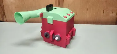
Operation is easy, simply stick a vacuum up to the cone on the exhaust manifold, and watch it rip! You may need to give it a rotate or two to help it get started.
Tips for success: Be sure that the camshaft if offset by a quarter turn from the crankshaft (explained in the instructions). Try lubing all of the areas where there is filament on filament contact, to reduce friction and increase speed and power. Clean out your vacuum's filter, or remove it entirely to improve your vacuum performance. Be sure there is little friction inside the crank case, as in make sure there are tiny gaps between all of the moving parts to ensure they move freely.
Updates:
I have many updates planned, from gaskets cutouts, to new exhaust manifolds for different vacuums. I will include links to them here as they are developed.
I just finished a throttle body for this engine, and you can find it here
Thank you for checking this model out, and if you enjoyed, please share with your friends and family! I love designing models like this, and yall's support keeps me going. It takes a lot of time and trial runs to design new models. This model was no exception!

Instructions:
This model can be a bit complicated, as there are many pieces, but personally I found it very fun to assemble, and very satisfying.
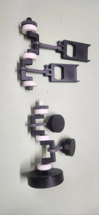
Step One:
Connect the piston heads to the connecting rods with the two pins. Next assemble the crankshaft. This can be a bit tricky, with all the pieces looking identical, but pay attention to the photo, and you'll do fine.
Note, the the position of the two cranks should be opposite, but I accidently had them the same in the first photo.


The parts include are the five crankshaft pieces, three 608 bearings, the two piston assemblies, the flywheel, and one of the two gears with a hexagon cutout.
Step Two:
Connect the two valves to the connecting rods with the two pins. Now assemble the camshaft, this can also be a bit tricky, since there are so many pieces that make up the camshaft. Again, just pay careful attention to the photos and you'll do great.
Note: If you get the crankshaft and camshaft pieces mixed up just remember the camshaft has a shorter stroke than the crankshaft, meaning the pieces are smaller.


The pieces used here are the five camshaft pieces, three 608 bearings, the two valve assemblies, and one of the two gears with a hexagonal cut out.
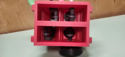
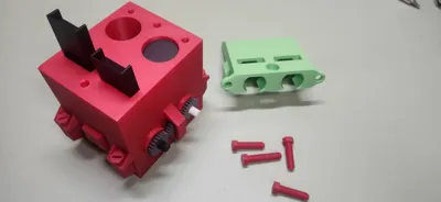
Step Three:
Attach the cylinder heads to the block. There are a different amount of each size of screw included in the file, and throughout the rest of these instructions I will refer to each screw by the amount of them that are included. The set of three screws go in the three holes in a line in the head, and the single screw goes in the single hole on the other side of the head.
VERY IMPORTANT: The screws included with this file are FRAGILE and cannot take very much twisting force at all. To avoid breaking off screws inside of the engine block or oil pan, finger tighten or lightly tighten with a flat-head screwdriver until its not easy and then STOP SCREWING.
Note that the screwheads are also 10mm, and you may be able to fit a socket on them, but you must still be very careful to not over tighten the screws.

Step Four:
Now it is time to lay the crankshaft, the camshaft, and the middle gear into the engine block. This step can be tricky, and must be done correctly or the engine will not function. The secret to vacuum engines is to have the camshaft a one quarter (0.25, 90 degrees) turn AHEAD of the crankshaft, in the direction you want it to rotate. In a simpler sense, this means that while the valve is completely open (Top Dead Center) the piston must be halfway up. When the piston reaches Top Dead Center, the valve with already be half closed. Additionally, since this engine has two cylinders, the pistons and valves must be in opposite positions to be most efficient. Finally, if you would like to mess around with tuning the engine for higher speeds, try changing the amount that the camshaft leads the crankshaft. Basically, try a lead of maybe a sixth of a turn or a third of a turn, instead of a quarter turn.

Step Five:
Once you've got those in place, you can carefully screw the oil pan to the engine block with the set of four screws included in the file. Be sure the quarter turn amount does not change while you set the engine block and the oil pan together.

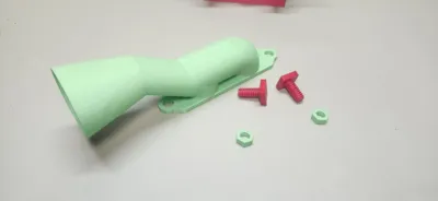
Step Six:
Finally, attach the exhaust manifold to the heads with the set of two screws, and the nuts. This may take some finagling to get them on. Once again remember to not overtighten, I advise only finger tightening.


Congrats! Your finished! Don't forget to share a comment with a photo about your experience, I love to hear about it, whether success or failure. Also don't forget to boost!
License
You shall not share, sub-license, sell, rent, host, transfer, or distribute in any way the digital or 3D printed versions of this object, nor any other derivative work of this object in its digital or physical format (including - but not limited to - remixes of this object, and hosting on other digital platforms). The objects may not be used without permission in any way whatsoever in which you charge money, or collect fees.
Comment & Rating (17)