Pixel Clock


Print Profile(1)

Bill of Materials


Description
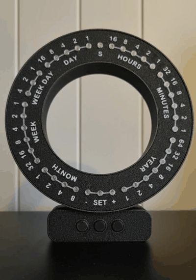
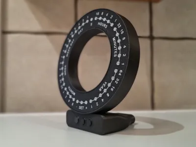
A Pixel Clock that shows time and date in a binary fashion.
I did this project a while back, and thought I could share it here.
There is a start-up routine when connected to power (as shown in gallery), then it functions as a calendar/clock.
Controls:
- +/- buttons control dimming.
- Holding the SET button enters the mode where you can adjust the time each subsequent press will toggle the different outputs.
- +/- for setting the values.
- Hold SET again for saving.
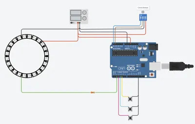
The clock is powered directly from the arduino via a USB cable.
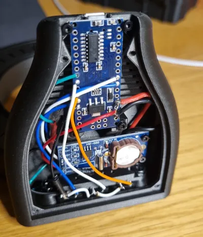
Bill of Materials:
- Arduino Nano
- WS2812 Pixel Ring 40 pixels (https://a.aliexpress.com/_EHkUGuy)
- Clock Module RTC I2C PCF8563
- 3x Microswitch P-B1729 (typically the ones that are included in Arduino Kits)
- 220 Ohm resistor
- Wires
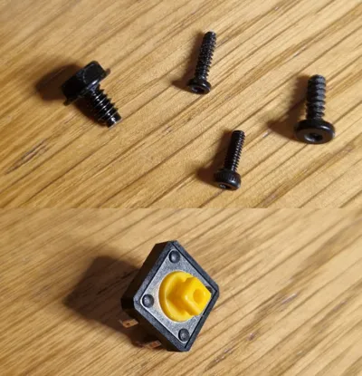
- Screws
- 4x Ø2x8 (bot plate)
- 6x Ø2x6 (el. components)
- 3x Ø2.6x8 (back plate)
- 4x Ø2.6x8 (front plate)
- 2x Ø3.5x6 (button holder) I used screws typically found in computer builds..)
- 2x Ø2.6x8 (base to ring)
- Buttons
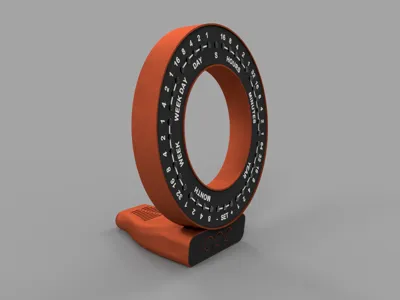
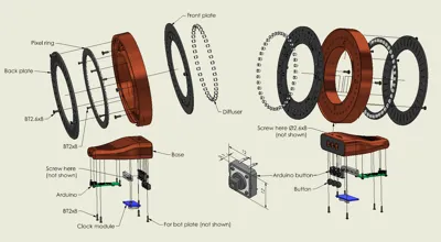
Assembly:
Various screws are used, mainly from the Bambu Makers Kit. The screw are intended to self thread into the plastic.
I have tried to indicate what screws I have used, but it is a long time since I assembled it myself and I don't have everything clear in memory..
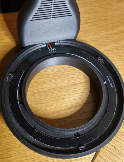
The back plate has a small shave on one side, align this with the base.
The ring itself is screwed onto the base by two screws entered from the inside of the base.
This is not intended as a tutorial for beginners. There is a massive amount of resources online where you can learn the basics.
Though requiring some soldering, this is not an advanced project.
My Arduino sketch and wiring diagram can be found attached. The wiring diagram is simplified, check the component documentation for wiring.
This was my first real arduino project, so I am sure it is not the most effective code. Still it does the job.
The FastLED library is used for controlling the pixels.
The current draw should be OK (minor amount of pixels lit at the same time), and the draw is also restricted in code.
However, care should be taken when dealing with electronics, and not to exceed the limits.
Disclaimer:
Do not attempt this build this if you do not have the required knowledge. I take no responsibility if anything were to happen.
Documentation (1)
License
You shall not share, sub-license, sell, rent, host, transfer, or distribute in any way the digital or 3D printed versions of this object, nor any other derivative work of this object in its digital or physical format (including - but not limited to - remixes of this object, and hosting on other digital platforms). The objects may not be used without permission in any way whatsoever in which you charge money, or collect fees.
Comment & Rating (7)