


Print Profile(1)

Description
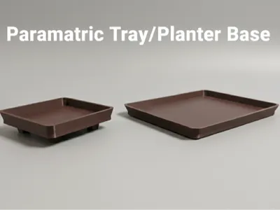
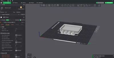
This project started when my father needed a specific rectangular saucer for a planter, and I couldn't find a suitable model anywhere. Instead of designing just one, I decided to create this fully parametric OpenSCAD model.
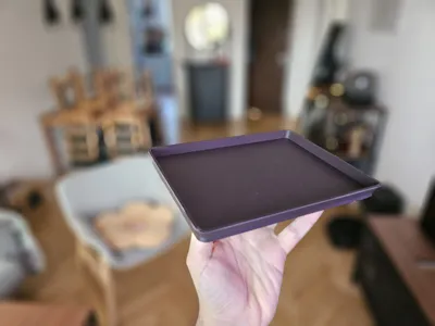
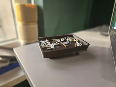
While its origin is a plant saucer, its uses are endless. For example, I printed a small version that I now use as a parts tray to hold screws and small components when I'm assembling or disassembling electronics.
It's designed to be simple, customizable, and functional. You can control all the key dimensions of the tray, from its internal size to the wall thickness and angle.
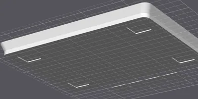
A key feature is the optional generation of four separate feet and the corresponding sockets (recesses) in the tray base. This allows for a clean look and easy assembly.
How the Sockets Work
If you choose to generate feet, the sockets are created dynamically based on the parameters you set for the feet.
- The script takes the base dimensions of the foot (foot_bottom_a and foot_bottom_b).
- It then adds the foot_recess_tolerance to these dimensions. This makes the hole slightly larger than the foot, ensuring it will fit even with printing inaccuracies.
- You can also control the depth of this socket (foot_recess_depth) and its position relative to the edge (foot_recess_margin).
Customization Parameters
This model is controlled entirely by the variables at the top of the .scad file.
📐 Internal Tray Parameters (Pot Dimensions)
These define the inside space of the saucer. You should measure the outer dimensions of your pot and add a little "wiggle room" so it's not a tight fit.
Example: If your pot's base is 100mm x 50mm, you might set these parameters to 105mm x 55mm (or 110mm x 60mm) to ensure it fits comfortably.
- a_dimension: The inner length (mm) of the tray.
- b_dimension: The inner width (mm) of the tray.
- h_dimension: The inner height (mm) of the walls.
🧱 Tray Construction Parameters
These define the physical structure of the tray itself.
- base_thickness: How thick the bottom plate is (mm).
- wall_thickness: How thick the side walls are (mm).
- flare_angle: The outward angle of the walls (in degrees). 0 means perfectly straight vertical walls.
- tray_corner_radius_inner: The radius of the inside corners (mm). The outer radius is calculated automatically based on this and the wall thickness.
🦶 Feet & Socket Parameters
These control the generation of the 4 feet and their matching sockets.
- generate_feet: (Important) Set to true to generate both the separate feet and the sockets in the tray. Set to false to generate only a plain, flat tray (no feet, no sockets).
- foot_height: The total height of the separate feet (mm).
- foot_top_a / foot_top_b: Dimensions of the foot's top (the part that touches the ground).
- foot_bottom_a / foot_bottom_b: Dimensions of the foot's base (the part that glues into the tray).
- foot_recess_depth: How deep the socket in the tray base is (mm). (Note: If this is larger than base_thickness, it will create a hole!). From my testing, a depth of 1mm is sufficient.
- foot_recess_margin: The distance from the tray's flat edge to the edge of the socket.
- foot_recess_tolerance: (Important) This adds "wiggle room" (e.g., 0.5mm) to the socket dimensions. In my experience, 1.0mm worked perfectly on my Bambu A1, giving a snug fit that was easy to glue. You may need to adjust this (e.g., 0.5mm) based on your printer's accuracy.

⚙️ Quality Settings
- $fn: Controls the resolution of the curves (like the corners). Higher numbers = smoother corners, but slower rendering.
🖨️ Print Settings
- Tray: The tray itself should print without any supports.
- Sockets (Bridging): If you use the feet (generate_feet = true), the sockets in the tray base are cutouts. Your printer must have good bridging settings enabled to print the "roof" of these sockets (which forms the inside floor of the tray).
- Feet: If enabled, the 4 feet are generated separately and should be printed flat on the build plate without supports.
🛠️ Assembly
(Only if generate_feet is true)
- Print one (1) Tray and four (4) Feet.
- Test the fit of the feet in the sockets.
- Apply a small amount of super glue or other strong adhesive into the sockets and press the feet firmly in place.
👨💻 A Note from the Creator
I'm an amateur designer, so this model might not be perfect and the OpenSCAD code might not be the most efficient! If you have expertise and see areas for improvement (e.g., better logic, new features), remixes are highly encouraged! Please feel free to fix, optimize, or adapt this design.
🚀 Like this model?
Boost Me (for free)
If you found this project useful, please give it a boost! It's much appreciated and helps other makers discover it.
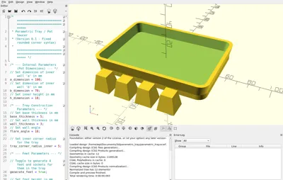
🖥️ Code
/* =======================================================
* Parametric Tray / Pot Saucer
* (Version 6.1 - Fixed rounded corner syntax)
* ======================================================= *//* --- Internal Parameters (Pot Dimensions) --- */
// Set dimension of inner wall 'a' in mm
a_dimension = 100;
// Set dimension of inner wall 'b' in mm
b_dimension = 70;
// Set inner height in mm
h_dimension = 10;/* --- Tray Construction Parameters --- */
// Set base thickness in mm
base_thickness = 5;
// Set wall thickness in mm
wall_thickness = 3;
// Set wall angle
flare_angle = 10;// Set inner corner radius for the tray
tray_corner_radius_inner = 5;/* --- Feet Parameters --- */
// Toggle to generate 4 feet and sockets for them in the tray
generate_feet = true;// Set foot height in mm
foot_height = 15;// Set dimension 'a' of a top surface of the foot (the part that rests on the ground)
foot_top_a = 10;// Set dimension 'b' of a top surface of the foot (the part that rests on the ground)
foot_top_b = 10;// Set dimension 'a' of a bottom surface of the foot (the part that contacts the tray)
foot_bottom_a = 15;// Set dimension 'b' of a bottom surface of the foot (the part that contacts the tray)
foot_bottom_b = 15;// Spacing between feet
foot_spacing = 10;// --- NEW RECESS PARAMETERS ---
// Depth of foot indent in mm
foot_recess_depth = 1;// Spacing from the tray's flat edge to the indent edge in mm
foot_recess_margin = 5;//
// --- MODIFICATION (NEW PARAMETER) ---
//
// Margin (tolerance) for the foot recess.
// Added to the foot dimensions (foot_bottom_a/b) to make the socket larger.
// Depends on your print quality (e.g., 0.5 or 1.0).
foot_recess_tolerance = 0.5;
/* --- Quality Settings --- */
$fn = 60;
/* =======================================================
* Model Logic
* ======================================================= */
// --- NEW MODULE: Rounded Square ---
/**
* Module: rounded_square
* Creates a 2D square/rectangle with rounded corners using minkowski.
* size = [width, height]
* r = corner radius
* center = true/false
*/
module rounded_square(size, r, center = true) {
if (r > 0) {
// Calculate dimensions for the inner square
_inner_w = size[0] - 2 * r;
_inner_h = size[1] - 2 * r;
// Ensure dimensions are not negative
// MODIFIED: Used max() function for valid OpenSCAD assignment
inner_w = max(0, _inner_w);
inner_h = max(0, _inner_h);
// Use minkowski sum to round the corners
if (center) {
minkowski() {
square([inner_w, inner_h], center = true);
circle(r = r);
}
} else {
// This implementation of minkowski is centered, so we translate
translate([r, r, 0]) {
minkowski() {
square([inner_w, inner_h], center = false);
circle(r = r);
}
}
}
} else {
// If r=0, just draw a normal square
square(size, center = center);
}
}
// --- TRAY Calculations ---
flare_offset_h = 2 * h_dimension * tan(flare_angle);
scale_a = (a_dimension > 0.01) ? (a_dimension + flare_offset_h) / a_dimension : 1;
scale_b = (b_dimension > 0.01) ? (b_dimension + flare_offset_h) / b_dimension : 1;
outer_a_base = a_dimension + 2 * wall_thickness;
outer_b_base = b_dimension + 2 * wall_thickness;
outer_a_top = outer_a_base * scale_a;// NEW: Calculate outer radius based on inner radius and wall thickness
tray_corner_radius_outer = tray_corner_radius_inner + wall_thickness;
/**
* Module: Trapezoidal Foot
* Generates a foot based on defined bottom and top dimensions.
*/
module trapezoidal_foot() {
if (foot_bottom_a <= 0.01 || foot_bottom_b <= 0.01) {
echo("ERROR: Foot bottom dimensions (foot_bottom_a/b) cannot be zero.");
} else {
scale_a_foot = foot_top_a / foot_bottom_a;
scale_b_foot = foot_top_b / foot_bottom_b;
linear_extrude(height = foot_height, scale = [scale_a_foot, scale_b_foot]) {
square([foot_bottom_a, foot_bottom_b], center = true);
}
}
}
/* =======================================================
* Generating Final Objects
* ======================================================= */// --- 1. TRAY ---
// Main 'difference' operation defining the tray
difference() {
// 1. Outer Solid (POSITIVE)
union() {
// a) Flat bottom
translate([0, 0, 0])
linear_extrude(height = base_thickness)
// MODIFIED: Use rounded_square
rounded_square([outer_a_base, outer_b_base], r = tray_corner_radius_outer, center = true);
// b) Flared walls
translate([0, 0, base_thickness])
linear_extrude(height = h_dimension, scale = [scale_a, scale_b])
// MODIFIED: Use rounded_square
rounded_square([outer_a_base, outer_b_base], r = tray_corner_radius_outer, center = true);
}
// 2. Inner Solid (CUTOUT / NEGATIVE)
translate([0, 0, base_thickness])
linear_extrude(height = h_dimension + 1, scale = [scale_a, scale_b])
// MODIFIED: Use rounded_square
rounded_square([a_dimension, b_dimension], r = tray_corner_radius_inner, center = true);
// 3. NEW SECTION: Foot recesses (NEGATIVES)
// Generated only if the flag is 'true'
if (generate_feet) {
// Check if the recess is deeper than the base
if (foot_recess_depth > base_thickness) {
echo(str("WARNING: Recess depth (", foot_recess_depth, ") is greater than base thickness (", base_thickness, "). This will create holes."));
}
//
// --- MODIFICATION (NEW LOGIC) ---
//
// Calculate the target hole dimensions, including the tolerance
recess_hole_a = foot_bottom_a + foot_recess_tolerance;
recess_hole_b = foot_bottom_b + foot_recess_tolerance;
// Calculate the recess center position (relative to the tray center)
// MODIFIED: Logic updated to account for the outer corner radius.
// The position is now relative to the start of the flat edge, not the outer extent.
//
// MODIFICATION: Uses 'recess_hole_a/b' for position calculation,
// to maintain the correct 'foot_recess_margin' (margin from the hole edge).
recess_pos_x = (outer_a_base / 2) - tray_corner_radius_outer - foot_recess_margin - (recess_hole_a / 2);
recess_pos_y = (outer_b_base / 2) - tray_corner_radius_outer - foot_recess_margin - (recess_hole_b / 2);
// Check if recesses are valid (don't overlap)
if (recess_pos_x < 0 || recess_pos_y < 0) {
echo("WARNING: Foot recesses are overlapping or positioned incorrectly due to large radius/margin.");
}
// Loop to generate 4 recesses in the corners
for (x_sign = [-1, 1]) {
for (y_sign = [-1, 1]) {
// We use 'translate' to set the XY position
// The shape is created from z=0 to z=foot_recess_depth,
// which perfectly cuts the tray bottom.
translate([x_sign * recess_pos_x, y_sign * recess_pos_y, 0])
linear_extrude(height = foot_recess_depth)
// This remains a square, as the foot itself is square
//
// --- MODIFICATION (NEW LOGIC) ---
// Uses the enlarged 'recess_hole_a/b' dimensions instead of 'foot_bottom_a/b'
square([recess_hole_a, recess_hole_b], center = true);
}
}
}
} // --- End of tray definition ---
// --- 2. FEET ---
// (MODIFIED CODE - Feet generated BELOW the tray [Y-Axis], centered [X-Axis])
if (generate_feet) {
// --- Y Position Calculations (NEW) ---
// Calculate the maximum Y dimension (at the top) of the tray
outer_b_top = outer_b_base * scale_b;
// Set the Y position BELOW the bottom edge of the tray, including spacing
// We use foot_top_b for consistency with the original code (even though it's foot_bottom_b at Z=0)
start_y = -(outer_b_top / 2) - foot_spacing - (foot_top_b / 2);
// --- X Position Calculations (NEW, for centering) ---
// Use spacing logic from the original code (based on foot_top_a)
step_x = foot_top_a + foot_spacing;
// Total row width measured from the center of foot 0 to the center of foot 3
total_row_width_centers = 3 * step_x;
// X position of the first foot (i=0) to center the row:
start_x_centered = -total_row_width_centers / 2;
// Loop generates 4 feet in a row (along the X-axis),
// centered at X=0,
// and shifted down (on the Y-axis).
for (i = [0 : 3]) {
// Translate in X (row), Y (constant position below), and Z=0 (plane)
translate([start_x_centered + (i * step_x), start_y, 0])
trapezoidal_foot();
}
}

License
You may create derivative works based on this object, provided that all such derivative works are published exclusively on the MakerWorld platform and include proper attribution to the original creator. You may not share, upload, host, distribute, or publish this object—or any derivative work of this object—on any other digital platform, marketplace, or distribution channel. Commercial use of this object and any derivative works is strictly prohibited. This includes, but is not limited to, selling, renting, sublicensing, or using the object in any context in which you receive monetary compensation or other financial benefits.
Comment & Rating (1)