X Cube


Print Profile(1)


Description
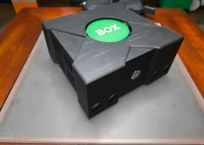
This cube shaped case topped with a large X might be vaguely reminiscent of consoles of a bygone era, but it's not and is definitely completely different and should in no way be considered as similar to them by anyone. The end resulting model should be about 7"x7"x3.5".
I used matte black [charcoal] for the body, and pla basic bambu green and white for the small jewel part.
Other parts are as follows:
sourced from ameridroid:
Odroid-H4 [just the base model as the other models have different io ports in the back]
15v power supply
NVME SSD 2tb
16GB DDR5 RAM
amazon:
dmwd: 16mm momentary push button switch ultra short halo ring green led
pzsmocn: dupont 200 pieces 2.54 mm pitch 1-pin adapter connector female housing black socket terminal
cerrxian: 120x120mm 3 pin pc fan green led [any 120x120 3-4 pin fan should work, but this specific fan powers the led and fan through the same plug]
saitech: it 4pk 15cm USB 3.0 extension cable to a male to female right angle 90 degree
fidioto: USB extension cable 1 male to 4 female
sdlqy: adhesive bumper pads transparent rubber feet
other parts:
m3x5: 4 used to hold the SBC to the base
m3x20: 6 used to hold the base to the sides and the back of the lid_bottom to the sides
m3x30: 4 used to hold the pc fan to the lid
Assembly:
read this all the way through and set everything together as if you were assembling it to be sure you have everything you need before you get started, and that you fully understand what you're doing
I used a USB to NVME adapter to write Batocera for PC to the 2tb ssd, then I mounted the nvme ssd, the ram, and the little rtc battery to the board [1 should come with the board without needing to order it .. but it's not mentioned anywhere].
I booted up the H4 after attaching it to my TV and after what felt like an eternity I got the little screen flash that let me know it had set itself up while I stared at the blank screen. When I rebooted it Batocera was running.
connect the metal dupont adaptors to all 4 wires coming off of the push button switch, test fit each one to be sure they have a snug fit before sliding the black plastic housing over it
mount the assembled H4 to the base using the m3x5 bolts, there should be some small amount of breathing room under the board
on the lid_bottom, remove the placeholder support print so that the center circle is lower than the rest of the top of the print. Carefully glue the lid_top to the lid_bottom, then use the m3x30mm bolts to mount the 120x120mm fan to push air up to the inside of the lid with the power cable off to the right side [front of console facing you]
on the sides, remove the placeholder support print in the back so that there is a gap as this will give access to the H4's io panel. Firmly push the USB 1 to 4 adapter female heads through the front of the item and ensure there is no filament hanging down in the way of the ports. Hot glue them in place from the inside. Slide the 90 degree extension cable halfway through the back of the item where the gap is that was created earlier, if your rtc battery cable is like mine then be sure to carefully slide the USB cable underneath it like in the image.
slowly lower the sides onto the base, ensuring your cable management is similar to what I have in the image. Once you get the sides to sit flat onto the base, connect the USB 90 degree cable to the H4 from the back, and then connect that to the 1 to 4 adapter. Sit the side and base parts on their side and use four m3x20 bolts to connect them together. Stick 1 of the rubber feet to each corner of the bottom of the base to help prevent the bolts from scratching any surfaces.
set the base and sides assembly down flat and then insert the power switch, make sure the nut is on the inside of the case so you can tighten it down. I looped them up in the corner and used a tie to keep them in place, then I realized there are no identifying markings for which set of cables is led power and which is the momentary switch. There's a tiny hole in the top and bottom of the inside of the switch plate, align one to face top and the other to face bottom as one side will be led power and the other side will be for the switch itself. LED power is easiest to test so I hooked up a black wire to pin 1 which is the 1st pin on the right as the board faces you, and red wire from the same side to pin 4 which is the 2nd pin up on the left side as the board faces you. On my installation nothing happened and I had to put cables from the other side of the holes in the back of the switch plate to those pins to get the led to light up when the board was powered on. There's a tiny power on and reset button on the board itself to help with testing. Then I took the two remaining wires and put black to pin 17 which is the 4th pin down from the back right side, and the red cable to pin 19 which is the 3rd pin down from the back right side. Note: Later on I checked and found the diagram calls for the reverse but I couldn't get it to work as the diagram calls for it.
If you use the extremely long switch from Ameridroid you would plug the blue wire into the 3rd pin from the end on the right side [19], the green wire in the 4th pin from the end on the right side [17], the black wire on the 1st pin on the right side towards the very front [1], and the red wire on the 2nd pin from the front towards the left side [4]. I initially used this but found I had to leave the switch sticking out of the case by a few millimeters to keep the wire protection from rubbing against the fan blades.
set the lid_top and lid_bottom assembly leaning against the left side of the side and base assembly and set up the fan cable so that it's just long enough to reach and the rest is bundled up nice and neat. Plug in the fan's power cable in the 4 pin coming out of the board right near where the switch was plugged in. The fan I'm using is a 3 pin so I just used the 3 last pins as shown in the image.
carefully rotate the lid assembly over, making sure to keep all your cables stay tucked away, and then gently rest it on the top of the sides and base assembly. There is a door latch style system at the front of the lid that will slide into place in the holes on the inside of the front of the sides piece. It might take a few tries to get it, but gently slide the lid assembly forward and down to get them to latch in place into the sides. It may or may not make a click or snapping sound as it slides into place.
use two m3x20 bolts to mount the rear of the lid to the sides and base assembly.
Comment & Rating (0)