HTMC Prime


Print Profile(2)

Bill of Materials


- 6-32x3.8 threaded brass heat inserts x 6: https://www.amazon.com/ruthex-6-32-Short-Threaded-Inserts/dp/B0DY6MNK8V/
- 12mm Power button x 1: https://www.aliexpress.com/item/1005005585121134.html
- 12mm Reset button x 1: https://www.aliexpress.com/item/1005005585121134.html
- PC screws kit x 1: https://www.amazon.com/gp/aw/d/B0DG2LFJP5
- Optional front USB ports x 1: https://www.amazon.com/GRAUGEAR-Internal-Required-Computer-G-MP01/dp/B09XV6XDLJ/
Description
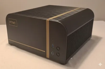
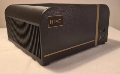
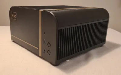
HTMC PRIME
Main features:
Designed to fit on top or inside TV furniture.
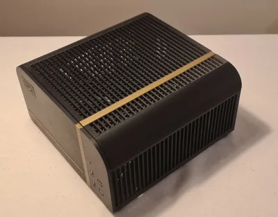
Good airflow in a compact case with multiple storage bay solutions for SSDs/HDDs.
Up to two 120mm fans in some configurations are possible.
CPU cooler height is max 48mm (from bottom of heatsink to top of cooler)
Support for entry/mid level GPUs (max length 270mm without HDD bay installed).
Easy to change logo text.
AMS is not needed (but makes better prints with support material).
Background:
I needed a PC case for my home theater and this is it.
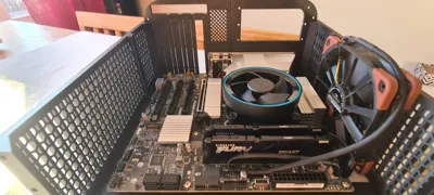
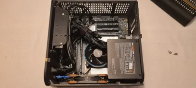
It’s built around a mATX motherboard and a SFX PSU while trying to keep it small but reasonably within specifications for the standard. I needed it to be not too deep as the TV cabinet is only 35 cm.
I’ll start off by saying that it’s probably not an economical way of getting a chassis but I made it for fun and it meets my criteria. Should you print it? Probably not, but if you like to tinker and don't need a large cooler for heavy CPU load or really high end GPU it could be right.
The areas where it is a bit restricted are at the CPU cooler height and also the GPU length.
Info:
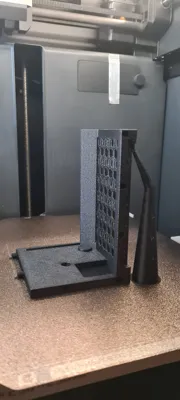
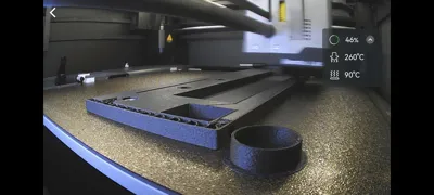
The model unfortunately does not fit the printbed of A1/P1S/X1C directly and needs to be glued together. I have tried to make the seams as invisible as possible on the surfaces that are the most noticeable and some parts are printed at angle which gives more print space and therefore doesn’t need to be glued.
My preferred material is ABS-GF as it is pretty dimensionally accurate and can stand reasonable heat for long periods. It gives a nice textured surface that hides some of the layer lines. It is also super cheap and easy to glue with pure acetone which you can find in almost every hardware store (at least here in Sweden). Apply acetone with a small brush on both sides and push them together for a couple of minutes. Leave it overnight and you have a physical bond between the parts that is as strong (or stronger really) as the single printed ones. If your surfaces are a bit rough you can use acetone and dissolved normal ABS to get a thicker substance that fills the gaps. Just cut standard ABS filament (or use purged/waste if you know it’s clean from other filament types) into smaller pieces and add to the acetone, leave it for a couple of hours and it becomes a slur. This is what I used on this model as some pieces had a little gap that I couldn’t get rid of. To print with ABS-GF it is recommended to use a hardened steel nozzle as it is abrasive.
Remember to have a well vented room if printing in the same building as you live in when printing ABS for extended periods. It is toxic and smells a bit.
And, yes! The included print profile uses supports. They are not always evil! ;-)
I also use Support Filament for ABS and PLA to get smoother surfaces on Front Plate and Logo Plate.
I’ve tried to stay within 1kg of filament on the main body so you should only need one roll for that. It’s on the edge, about 900g so if some prints go bad you might need another roll of course. Then there are some extra parts like trim which could be any material of choice, even PLA should work, about 20g. And TPU parts for feet and dampers, about 15g.
There are mounting options for a 120mm fan on top and one on the side around the CPU.
It comes with 3 different HDD/SSD bay configurations if needed. The ones for HDD are softmounted with TPU. If the largest HDD bay is used, the top mounted fan will not fit and probably not the motherboard connectors for front USB either. Mine did not anyways.
For the front USB-connectors I used something I had from an earlier project and modded it to fit. As it’s not a standardized item I have not provided it in the main print profile, there simply are no holes for USB included right now.
If you'd like to use the exact same USB-ports and mod them to fit, I’ve included a front plate in a separate file and a link to the specific ports. There might be space to the left of the Power and Reset button to maybe squeeze in a 3.5” front plate module (the ones that go in the hole where really old cases had a floppy drive). The problem is there is not that much space inwards. Connectors and memory modules will probably be in the way for the tray. As the model is free to remix, I leave that to the one who needs it to complete the task.
Materials needed:
ABS or ABS-GF for main parts, (preferred, but the choice is naturally yours) around 900g
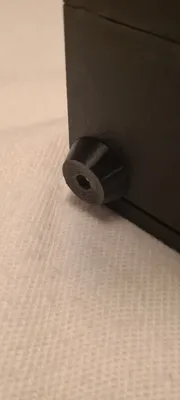
TPU 95HF for feet and vibration dampening, (or other softer TPU) 20g
PLA for trim pieces, (or whatever material you think looks nice for the trim) 15g
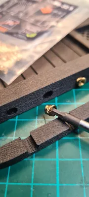
6 pcs of 6-32x3.8 threaded heat inserts for the PCIe brackets and the Lid
2-4 pcs of M3x6x5 threaded heat inserts for the HDD bay
4 pcs of M3 nut
4-8 pcs of M3x10 machine screw (socket head or hex head)
25 pcs ca of PC screws for Motherboard/PSU/HDD and Lid
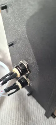
1 pcs of 12 mm Power button
1 pcs of 12 mm Reset button
I used these:
https://www.aliexpress.com/item/1005005585121134.html
Optional:
Front USB ports to mod, same as I used on my build:
https://www.amazon.com/GRAUGEAR-Internal-Required-Computer-G-MP01/dp/B09XV6XDLJ/
Assembly Instructions:
If you’re using ABS in any form I really recommend preheating your cabinet.
It's a really good idea to purge any low temp filament (PLA) from the extruder before preheating as there's a pretty high chance of getting a clog if the heat creeps up above the nozzle. Easiest way is to load the ABS manually from app and purge some of it so you are sure there is no leftover from previous filament. Park the head above the waste chute.
On my P1S I usually throw a blanket over the whole thing, lower the build plate to the middle, set the AUX FAN to 40% and then set the build plate to 100°C.
When the nozzle temp reads above 45°C it's ready to print.
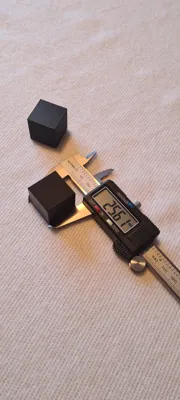
Print a test cube and calibrate the filaments shrinkage as per this guide:
https://wiki.bambulab.com/en/knowledge-sharing/3d-prints-shrinkage
Print all the parts.
The four bottom pieces pause for insertion of M3 nuts at the corners, the holes to use are the only hexagonal ones so it’s hard to miss.
Insert them carefully, not bumping anything and then press play to resume the rest of the print. The holes for the nuts should be plenty oversized so they should go in easily without force.
Have patience and let everything cool properly before opening the printer and removing the build plate. Especially important if you use more complicated filaments like ABS/ASA. The parts fit badly if they warp. If you use the included print profile and ABS-GF there are tweaked settings for temperatures and cooling on the P1S. This way you should not need glue on the build plate and the overhangs look better.
Check that all pins and holes work as intended so that the pieces go together without hesitation. I did not need to sand any pins but that may not be the case for you. Better to work out all that before you start to glue.
Glue the Bottom Plates together.
Join the front pieces together and then the rear pieces and last join front and rear assemblies.
Figure out where the standoffs need to be according to the motherboard manual. Screw the printed motherboard standoffs into the bottom plate as your setup requires. They can be a little fiddly/hard to get into place but should work without any modification. They should be flush with the underside of the Bottom Plate.
Take a moment to think through if you need to cut out any of the plates on the Bottom Plate.
They are only held in place with 0.4 mm so should be easy to cut out with an Exacto knife. There is a hole already included which is necessary for the side mounted fan as it goes all the way to the bottom.
Add the machine screws (M3x10) through the feet and screw them onto the Bottom Plate where we added nuts earlier.
Glue the Front Plate together.
Insert the heat inserts (M3x6x5) to the HDD bays mounting points if you intend to use one.
Be careful not to go too deep as it will show on the Front Plate.
Mount the Power/Reset buttons (and USB ports if available).
Glue the Front Plate to the Bottom Plate.
Glue the Back Plate together.
Insert the heat inserts (6-32x3.8) to the PCIe mounting bar and Lid lock.
Now you can choose to glue the Back Plate to the Bottom Plate or just use screws.
The screw option is so that you can later choose to swap it out. I’m planning to release a bottom expansion for the case if you want to use a standard ATX PSU and have more/better cooling for HDDs/SSDs. Then the back plate will look a little different without the mounting for the SFX PSU and more grid/holes for airflow. If that’s not important, glue it!
Glue the Top Plate together.
Add the fans as needed, to the Top Plate and to the side of the Bottom Plate.
If your motherboard has a separate back plate cover, don’t forget to attach that before the motherboard.
Mount the motherboard. As the standoffs are printed, it doesn’t take much to overtighten the screws, so be careful. It’s meant to work a couple of times and with moderate force. In return we don’t need heated inserts everywhere.
Connect buttons and fans to the motherboard.
Mount SSDs and/or HDDs to the bay that you have chosen.
Add dampeners to the bigger bays if you're going to use HDDs. It just slides into the C-slots of the bay. The bigger dampener end is meant to go against the mounts on the Front Plate. The dampeners may not do that much for noise but it can’t hurt to try to mitigate as much as possible. It's an all plastic case after all and amplifies most of the vibrations.
Mount the chosen bay with the M3x10 machine screws, tighten until the dampeners are just a little bit squished. The bay should feel secure even with heavy HDDs. You need to grab and “feel it in” a little to see if you think it would hold. I have 2 HDDs and it feels solid but I will not be held accountable for any HDD failures you have if they fall out.
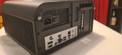
Add the PSU to the Back Plate with regular PC screws and connect it.
Cut out the covers for the PCIe-slots you intend to use and install the cards.
Put the Lid on and you should be done!
Much of the planning and measurements derive from the excellent work of
Shashank Chintalagiri’s reference models:
https://grabcad.com/library/generic-atx-matx-mitx-thinitx-motherboards-1/details?folder_id=4666432
Happy Printing!
License
You may create derivative works based on this object, provided that all such derivative works are published exclusively on the MakerWorld platform and include proper attribution to the original creator. You may not share, upload, host, distribute, or publish this object—or any derivative work of this object—on any other digital platform, marketplace, or distribution channel. Commercial use of this object and any derivative works is strictly prohibited. This includes, but is not limited to, selling, renting, sublicensing, or using the object in any context in which you receive monetary compensation or other financial benefits.
Comment & Rating (0)