Ionic Wind Generator + Testing Base Structure


Print Profile(6)


Bill of Materials

- Stun Gun Module x 1: https://de.aliexpress.com/item/32737738904.html
Description
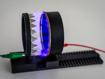
Ionic Wind Generator
This project demonstrates how to generate ionic wind using only a high voltage of 10–20kV!
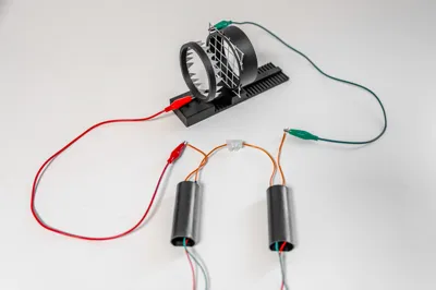
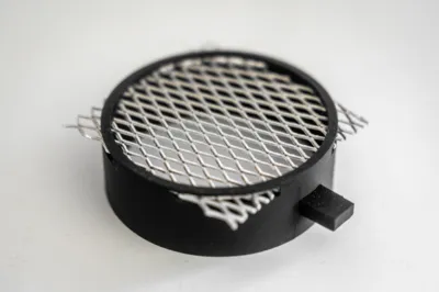
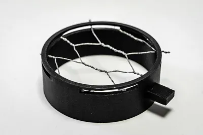
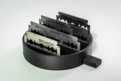
To achieve this, I used a stun gun module (≈20kV), which can be sourced cheaply on AliExpress (see parts). I designed 10 different electrode geometries and tested various combinations to determine the most efficient setup. Based on my experiments:
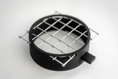
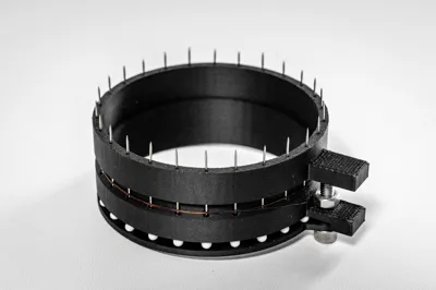
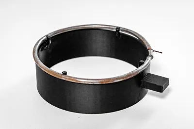
- The best performance came from using needles as the first electrode and a ring as the second electrode.
- For maximum airflow, the first electrode (i.e. needles) should be positively charged and the second electrode (i.e. ring) negatively charged.
- If you invert the polarity, you can enjoy a beautiful blue corona discharge (best viewed in the dark).
Electrode Mounting System
I designed a modular baseplate with:
- A fixed mounting point for electrodes.
- A rail system for adjusting electrode distance.
Two gantry versions are included:
- Toothed gantry → allows distance adjustments in 5mm steps.
- Smooth gantry → allows fine adjustments using a ruler.
From my tests, the optimal electrode gap corresponds to the spark length the used voltage can achieve (approx. 1mm per kV). For example, at 20kV, the ideal distance is about 20mm.
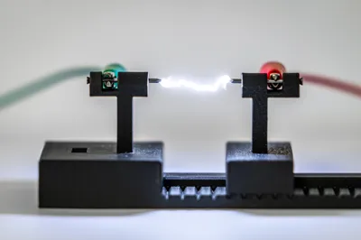
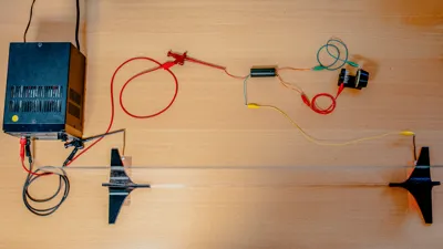
Voltage Measurement Setup
I also designed a holder for two nails that can act as spark gap probes to estimate the transformer’s output voltage:
- Mount the nails on the gantry and baseplate.
- Connect them to the transformer with crocodile clips.
- Slowly increase the input voltage until a spark jumps the gap.
- The arc length corresponds to the output voltage (≈1000V per mm).
Safety Notice ⚠️
This project involves high voltage, which can be extremely dangerous. Sparks can jump further than expected, so always exercise caution. Additionally, running the device can produce ozone, so make sure your workspace is well-ventilated.
To enhance safety, I designed mounting feet for a plexiglass shield, which I strongly recommend printing and using. Any 3D printing filament will work for the parts, and PLA is perfectly sufficient.
License
You shall not share, sub-license, sell, rent, host, transfer, or distribute in any way the digital or 3D printed versions of this object, nor any other derivative work of this object in its digital or physical format (including - but not limited to - remixes of this object, and hosting on other digital platforms). The objects may not be used without permission in any way whatsoever in which you charge money, or collect fees.
Comment & Rating (1)