Search models, users, collections, and posts

WalkingTable

IP Report

Print Profile(2)

All
X1 Carbon
P1P
P1S
H2D
P2S
X1E
H2D Pro
A1
X1
H2C
H2S
X2D
A2L
A1 mini

The Walking Table
The Walking Table
Designer
57.1 h
15 plates
5.0(12)

Controller
Controller
Designer
8.3 h
4 plates
5.0(10)

Open in Bambu Studio
Boost
1851
3545
181
158
626
119
Released 

Bill of Materials

Maker's Supply Kits and Parts
Select all
BT3x8 SHCS Self Tapping Screw (20PCS) - AA108
BT3x20 SHCS Self Tapping Screw (10PCS) - AA111
BT2x8 SHCS Self Tapping Screw (20PCS) - AA094
MR128ZZ (6PCS) - EA004
D6x2 mm Round Magnet (20PCS) - CA004
030 Micro DC Motor with SH1.0 (2PCS) - LA024
1:105 Single-axis (1PCS) - LA022
Beginner Hardware Kit - ZK004 (1 Vehicle 1 Remote)
Single-Axis Joystick Module (1PCS) - XA009
50mm Wire Pair with SH1.0(5PCS) - IC005
SH1.0 to Dual SH1.0 Adapter (2PCS) - ZH090
Bambu Filaments
Select all
Onyx Black Sparkle (13101) / Filament with spool / 1kg
Crimson Red Sparkle (13200) / Filament with spool / 1kg
Iridium Gold Metallic (13400) / Filament with spool / 1 kg
Clear (32101) / Refill / 1 kg

Description

[Introduction]

My rendition of the Walking Table. A fun little model based off of the strandbeest mechanism. This model utilizes the Cyberbrick hardware to come to life. Featuring a industrial inspired controller.


The first prototype print of the legs. The original legs included bearings for all the joints, but this was changed in favor of the simpler and cheaper approach.

The model itself has gone through several iterations. 


[Updates]

11/11/2025 - There's a known error in the documents in Step 1. I can't easily update the documents themselves right now because the software I used to create this version of the manual, with the animations, I don't have a license to anymore at the moment. Part of the joys of subscriptions, you know. 


I've added notes below, but just keep it in mind. The bearings should be inserted into the gears. They are illustrated on the wrong side of the gear, in the documentation. Please accept my apologies for that. 


I've also updated the print profile to fix an issue in there with one of the links being misplaced off of the build plates. Not sure exactly what happened there. 


Lastly, did some videos to show it off, and added those at the top!


[Hardware & Filament]

Featured Filaments:

  • Bambu PLA Onyx Black Sparkle
  • Bambu PLA Crimson Red Sparkle 
  • Bambu PLA Iridium Gold Metallic
  • Bambu PETG Transparent Clear (Used for the LED indicator on the controller)

Hardware:

Some of the required hardware will be part of the Cyberbrick kit. The hardware used specifically from the kit will be listed separately below for your reference.  

  • 1 Cyberbrick Kit
  • 105 x M3x8 Self Tapping Screws
  • 20 x M3x20 Self Tapping Screws
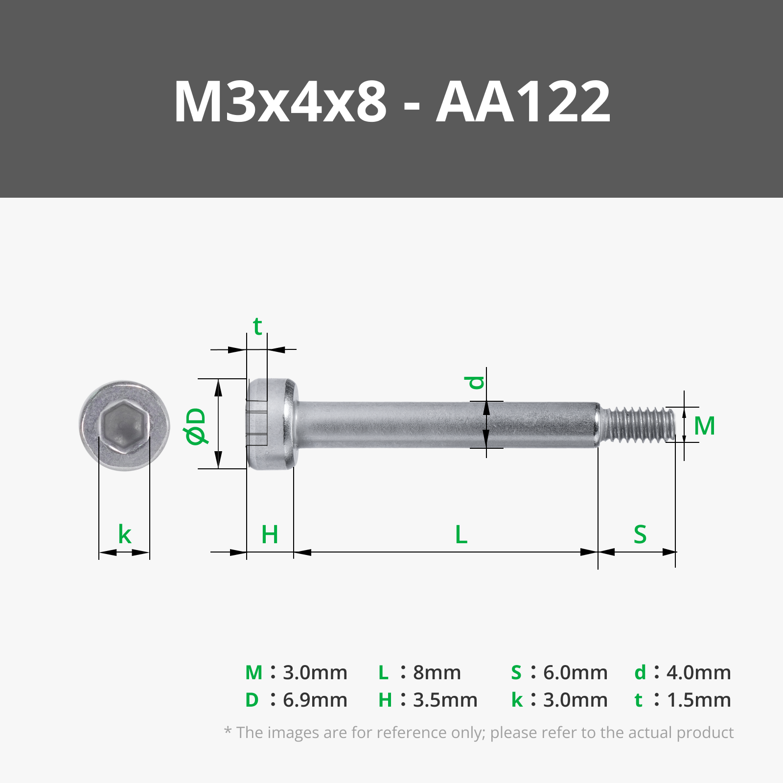
  • 36 x M3x4x8 Shoulder Machine Screws
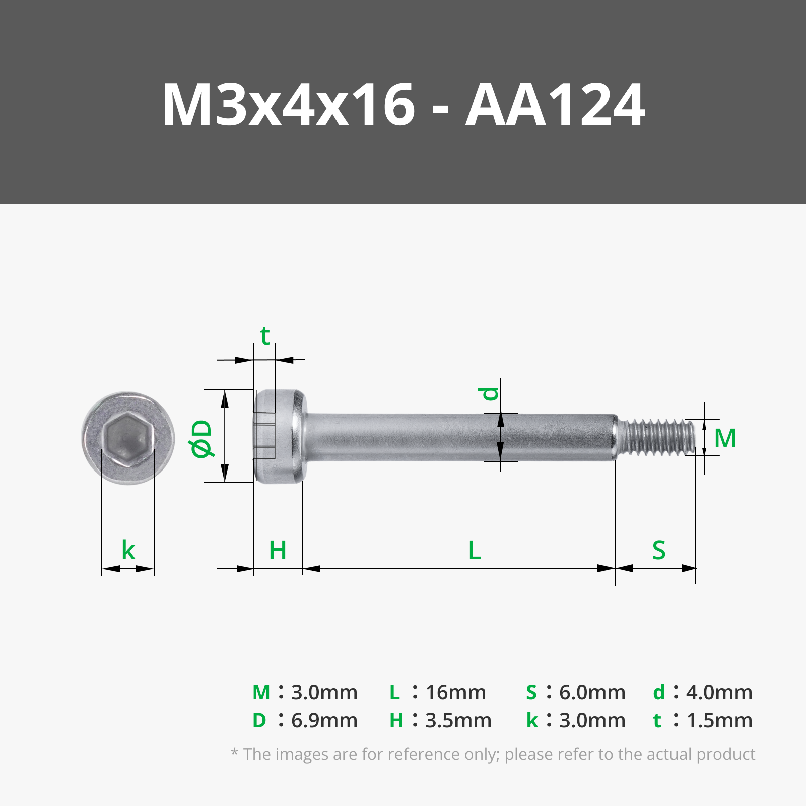
  • 36 x M3x4x16 Shoulder Machine Screws
  • 13 x M2x8 Self Tapping Screws
  • 18 x MR128ZZ Bearings
  • 2 x 030 Mcro DC Motors (Please note, there's 4x030 motors used in total, two of which are part of the standard Cyberbrick Kit)
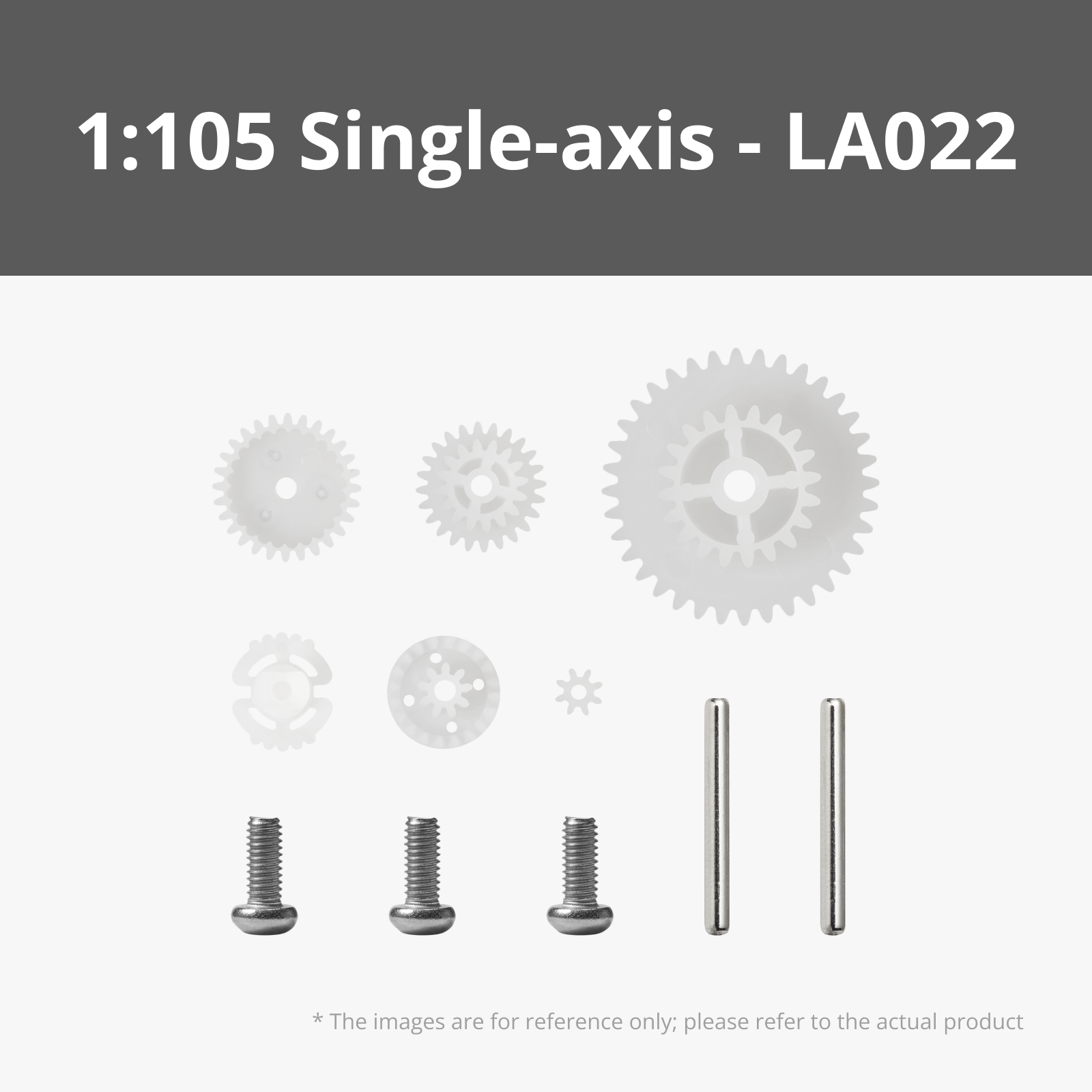
  • 4 x Gear Reduction Sets (1:85 or 1:105 recommended)
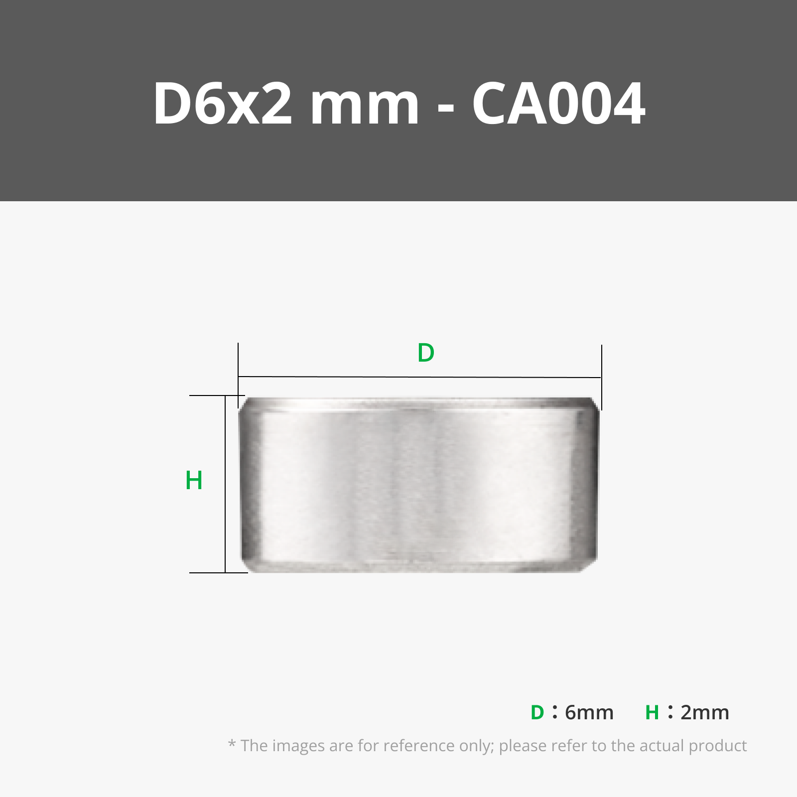
  • 4 x 6x2 Magnets
  • 2 x 1to2 Terminals
  • 1 x  Single-Axis Joystick Module 
  • 2 x 50mm wire with SH1.0 connectors

Hardware used from the Cyberbrick Kit:

This is the hardware we'll use specifically from the kit. Purchasing the kit should be slightly cheaper then buying the needed components separately.

  • 2 x Multi-Function Controller Core
  • 1 x Remote Control Receiver Shield
  • 1 x Remote Control Transmitter Shield 
  • 1 x Power Switch Module
  • 1 x Single-Axis Joystick Module 
  • 2 x 100mm Wire with 3Pin SH1.0 Connectors
  • 1 x 3x1.5V AAA Battery Case with XH2.54 Connector
  • 1 x 14500 7.4V 800mAh Li-ion Battery
  • 1 x 7.4V Lithium Battery Charger with XH2.54 Connector
  • 2 x 030 Micro DC Motor
  • Lubricant Grease


A few notes on the hardware. We're using 4 of the 030 Micro DC motors, two of which are included in the beginner kit. The controller will make use of two single axis joystick modules too, but only one is included in the kit. 


[Assembly]

The assembly guide is a work in progress and will be updated over the next couple of days. Here's the first section, covering the main assembly. A PDF version will be added when the full assembly guide is completed.


[The Main Table]

Insert the short axles into the frame on either side and secure them using screws. Insert the MR128ZZ bearings into the gears, Install the gears and secure them with screws onto the axles. Don’t forget the decorative washers. Besides looking good, they help secure the main gears

There are 3 versions of the leg frame. The outer, mid, and inner. The mid frame has wider mounting holes, and the inner frame has mounting holes for the motor. You should have 2 of each, for 6 total.

(Warning: There's an error in the image that shows the bearing on the wrong side of the big gear. The bearing should be inserted into the big gear, not sit between itself the gear and the frame.)

(Warning: There's an error in the image that shows the bearing on the wrong side of the big gear. The bearing should be inserted into the big gear, not sit between itself the gear and the frame.)

It’s time to assemble the legs. Using 3 M3x4x8 Screws and 3 M3x4x16 screws we’ll connect the leg links together and secure them to the frame. Using 2 additional M3x8 Self tapping screws, we’ll attach the feet. All link sections should have their bed side faces towards the frame. 
Next we’ll assemble the motors so we can attach them to the appropriate leg frames. On either side, we’ll insert 2x030 Micro DC Motor along with the chosen gear reduction sets.   We’ll secure the top plate in place using the M2.5 screws supplied with the gear reduction sets.  Lastly we’ll install the small gears. The gears can be secured using M2.5x6mm screws, however it’s not required as the spacing of things will keep it in place.  Installing the small gear on both sides can be tricky, just wiggle and push it, and it’ll pop into place.
We’ll attach the motor to the interior frame piece with 4 M3x8mm self tapping screws
We’ll insert the leg assemblies into the frame sections, then secure them in place using 6 M3x20mm Self Tapping Screws  Take note that the leg assembly with the motor goes on the side of the frame with the 6 mounting holes
Now the tricky part. We need to slide the main axle in and slot the gears into place at the same time, while alinging the legs for each section. We want to make sure each leg section is at a different spot in it’s walk cycle, but that the gears are correctly aligned for a given leg set.   When you push the gear in, try to align the gears so the attachment points are pointing outwards or inwards once the gear is fully inserted. You’ll have to alien the axle too, so the flat side of the axle matches the gear.  Secure the axle into place with the 2 M3x8mm screws. 
At this point in the build, we should have two complete leg halves. We’ll combine them together by securing them to the center section with 12 M3x8mm Self Tapping Screws. The leg sections are symmetrical, so they can be placed on either end. 
We’ll secure the top plates to the frame using 16 M3x8mm Self Tapping Screws  (The legs have been hidden to better illustrate where the screw attachment points are)
For the electronics cover, we’ll insert 4 M3x8mm Self Tapping screws into the frame. For the cover, we’ll insert 4 D6x2mm Magnets. If needed, secure them with glue. 
Make sure to test the electronics before you secure them in place.  Feed the motor wires up through the central hole and start to route them around the case. Each side has two motors which will tie together using one of the 1to2 terminals for each side and the 50mm wire to connect it to the main board. Using the illustration, connect the left and right motors to the ports indicated.   Once everything is looking good, secure the electronics in place with 5 M2x8mm Self Tapping Screws. 
Lastly, once the electronics are installed, we’ll install the wire guard. Carefully slip it over the wires then secure it in place with 2 M3x8mm Self Taping screws. 


[The Controller]

We’ll start by inserting a M3x8mm self tapping screw into the main casing where the battery compartment is. We’ll insert a D6x2mm magnet into the battery cover. 
We’ll use 8 M2x8mm self tapping screws to secure the electronics in place. Make sure the ports for the sticks face forward, and the battery port on the transmitter shield faces towards the back.   You can place the battery pack, and then secure it in place with the cover while we route the wires. 
We’ll route the wires. Use 2 of the 100mm 3pin wires included with the cyberbrick kit to connect the joysticks to the transmitter shield. Route the battery pack’s wire around and plug it into the shield too.
We’ll attach the top handle/guard using 3 M3x20mm Self Taping screws.
We’ll start to assemble the top plate. We’ll secure the LED indicator piece in place by passing through 2 of the M3x8mm screws into it. The other 4 screws will attach the stick plates directly to the top face of the controller. 
Finally, we’ll attach the top plate to the base of the controller. We’ll secure it using 4 M3x8mm Self Taping Screws. Once the top plate is in place, we can push the control knobs onto the joysticks.

-------

If you like my work, consider showing your love by Buying me a coffee. Additionally, if you're looking to sell prints of my design, please check out my Patreon page for more information.


Documentation (2)

Assembly Guide (2)
Controller_Instructions.pdf
WalkingTable_Instructions.pdf

CyberBrick Files (1)

FAQ
Official RC Framework
WalkingTable

Comment & Rating (181)

(0/1000)

License

This user content is licensed under a Standard Digital File License.

You shall not share, sub-license, sell, rent, host, transfer, or distribute in any way the digital or 3D printed versions of this object, nor any other derivative work of this object in its digital or physical format (including - but not limited to - remixes of this object, and hosting on other digital platforms). The objects may not be used without permission in any way whatsoever in which you charge money, or collect fees.

Related Models

There are no related models yet