
Capsule Vault - Combination Lock


Print Profile(5)


Bill of Materials
Description
Capsule Vault - Combination Lock
The Capsule Vault is a compact and secure storage solution with a combination lock designed to complement the modular Travel Capsule, which is available in various sizes. It features a 4-digit combination lock mechanism with four numbered dials, offering 10,000 possible password combinations for enhanced security. The password can be fully customized by repositioning the outer dials during assembly, allowing for flexibility and personalization.
To unlock the vault, dial the correct combination, and the spring-loaded mechanism engages, allowing the cap to lock into the thread. This enables the thread to turn and the container to open. When the wrong code is dialed, the cap continues to slip, preventing the thread from engaging and keeping the container securely locked. To lock the vault, simply turn two of the dial rings in opposite directions, reactivating the locking mechanism.
Two options are available for the internal spring: a 3D-printed PLA spring or adapters for metal springs. Metal springs are recommended, as PLA springs will lose their elasticity after a short period of time due to constant compression (creep). The printed spring is intended solely as a temporary solution to get started quickly for testing and experimenting with the mechanism if metal springs are not immediately available.
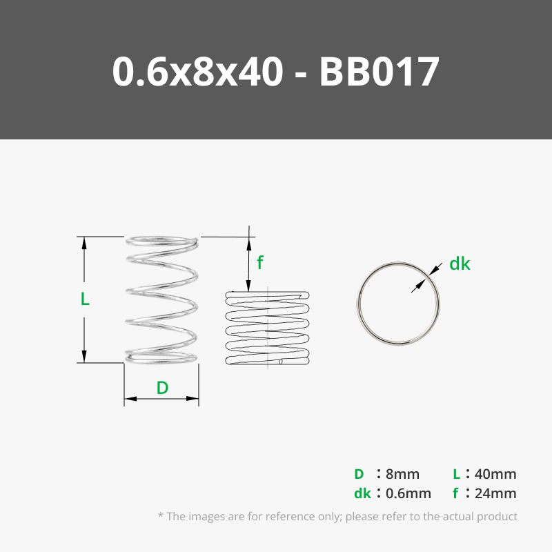
For the prototype, I used metal springs sized 7.5 x 35.8 x 0.7 mm. Springs from Bambu Lab's Maker's Supply have also been tested and work well with this setup, particularly the 0.6 x 8 x 40 mm springs (BB017).
Video Tutorial

Assembly Instructions
- Assemble the Dial Rings
Combine the outer and inner dial rings. The notch on the top side of the inner dial ring serves as an orientation marker, indicating the relevant number for the pin code.
- Attach the Core Component
Place the "core" component, which has the lock pins, onto the bottom plate with the thread around it.
- Insert the Center Screw
Pass the center screw through the bottom of the assembly.
- Install the Dial Rings
Place the assembled dial rings onto the "core" component. The rings will only fit in one correct position. After placing all the dial rings, verify that your desired pin code is aligned. Here my pin is going to be “8392”.
- Insert the Spring (two Options)
Insert the spring into the slot on the center screw. Ensure the side with the beveled edges is facing downwards.
- PLA/PETG version (not recommended for permanent use)
There are two different lengths of the PLA spring in my print profile. It seems the long version works better for most people.

Metal spring (7.5mm x 35.8mm x 0.7 mm)


- PLA/PETG version (not recommended for permanent use)
Attach the Cap
Place the cap on top of the assembly. It fits in two positions, so ensure the marking on the side of the cap aligns with your desired pin. When pushing down the cap, it will push out the center screw from the bottom. Hold the entire assembly in your hands during this step. If the assembly is lying on a flat surface, the screw on the bottom cannot be pushed out properly.
Secure with the Screw
Finally, screw in the center screw from the bottom to secure the entire assembly.

Problem Solving / FAQ
- Problem:
- If turning the rotary dials feels stiff or won’t move at all
- Solutions:
- Make sure the inner dial is oriented correctly.
- If necessary, apply a small amount of lubricant to the middle piece (the “core component”) to reduce friction.
Boost Me (for free)
If you enjoy this design and want to support my work, please consider boosting my models. Your support helps me create more unique designs. Thank you!
Please also check out my other models


License

You shall not share, sub-license, sell, rent, host, transfer, or distribute in any way the digital or 3D printed versions of this object, nor any other derivative work of this object in its digital or physical format (including - but not limited to - remixes of this object, and hosting on other digital platforms). The objects may not be used without permission in any way whatsoever in which you charge money, or collect fees.


Comment & Rating (206)