
Big Wall Clock

Print Profile(1)

Bill of Materials
- Double_Sided_Tape x 1: 700mmx12mm(1/2")
- Screw/Fixing x 1:
Description
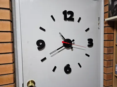
When I got my A1 printer, the clock components kit-011 was included in the packaging. I wasn't sure what I was going to do with it until I noticed recently that a clock design contest had been started.
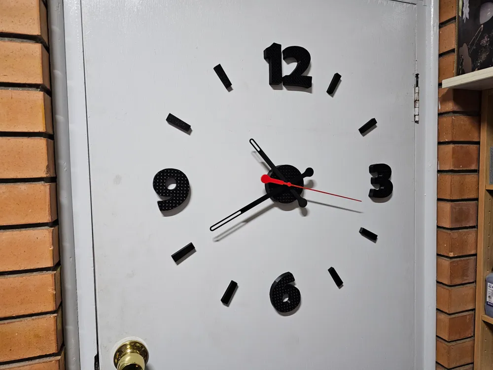
That got my attention, and I thought I would see if the clock was able to work successfully with larger hands.
Hence this big clock. The central hub, numbers and hour ticks have been printed with a single wall and gyroid infill. Please Note - the gyroid will not be seen until the print has been sliced. The hands have a single outer surface and 100% infill.
The print comprises of four plates:
- Main holder, ‘slim’ hour hand and minute hand, washer, template and template arm
- Numbers for 3, 6, 9 and 12, 8 x hour tick marks - gyroid pattern once sliced
- Second/sweep hand (optional)
- Alternate ‘wider’ hour and minute hands
If using the wider version hands, simply remove the slim version ones from the first plate before slicing.
The clock centre/hub requires a single screw type fixing and the numbers and hour ticks were installed with 12mm (½") wide double sided tape. I double sided taped the hour ticks with the textured plate surface facing out (gyroid facing surface). They could be put either way.
Assembly
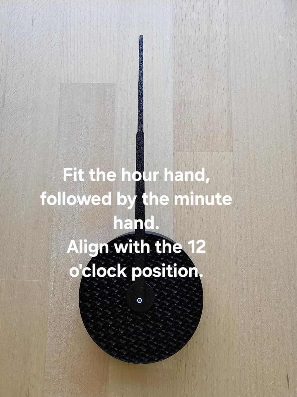
Once the parts have been printed and support material removed from the main holder: Photos have been added to show these steps.
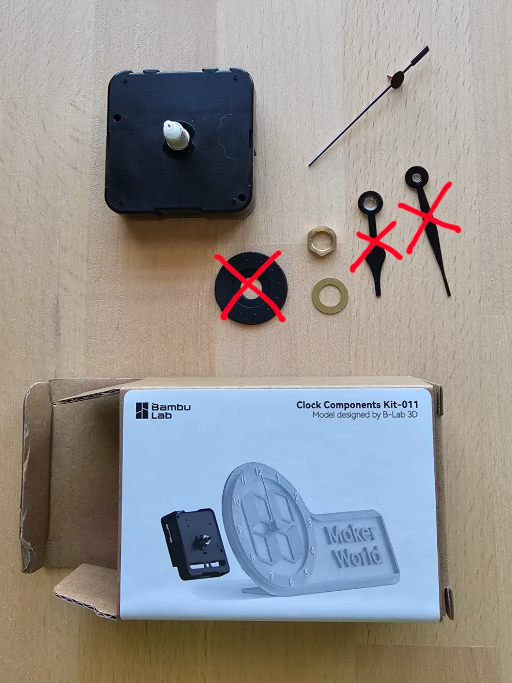
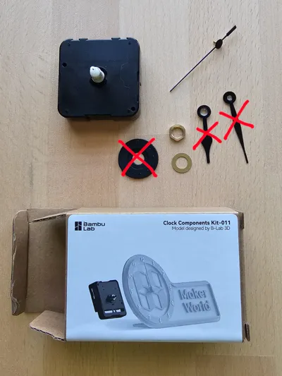
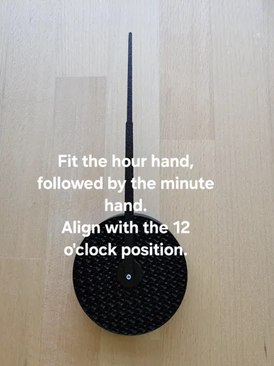
- open the clock kit and remove the hour hand, minute hand and rubber washer (these will not be needed).
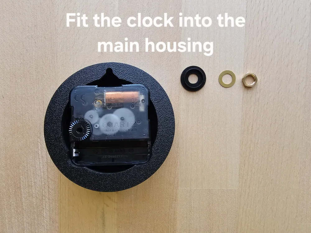
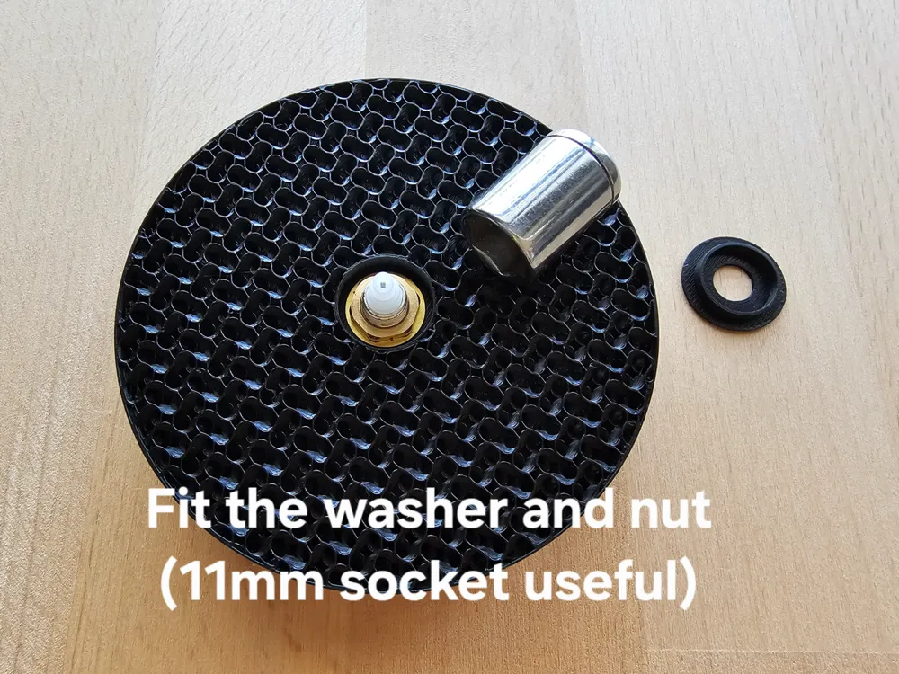
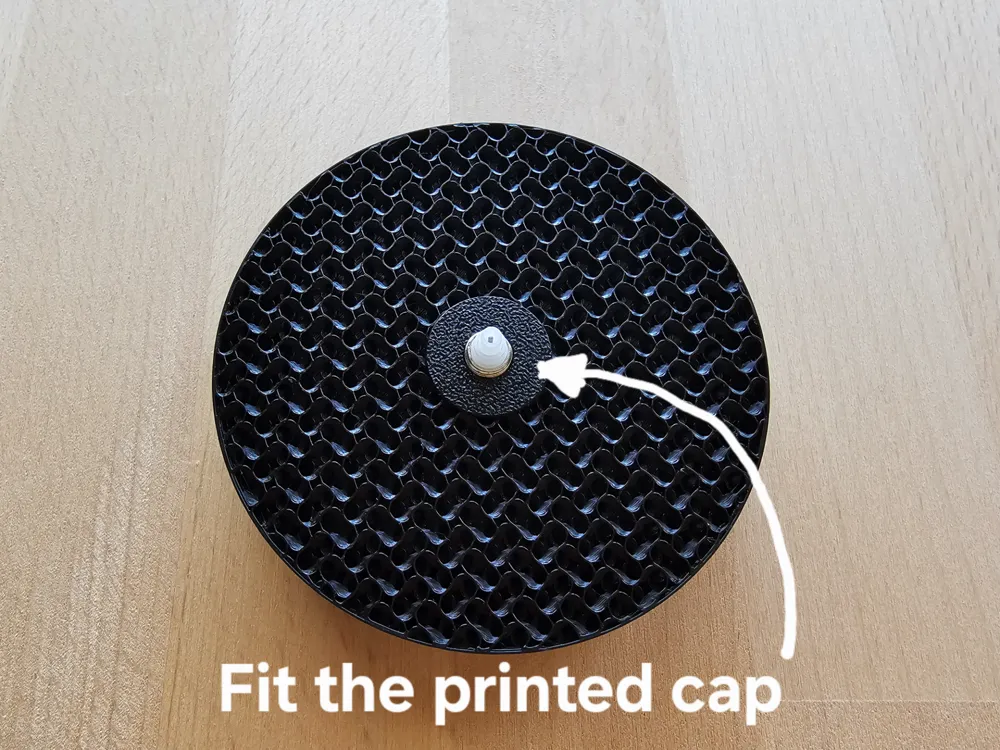
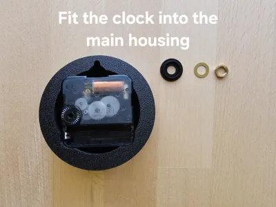
- Insert the clock mechanism into the open side of the main holder and secure into place with the brass washer and brass nut from the component kit. A thin wall 11mm socket works well here. Orientation of the clock mechanism will not matter - I placed the battery compartment at the bottom.
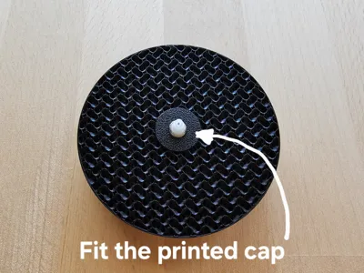
- Place the printed washer onto the clock shaft to hide the nut and washer.
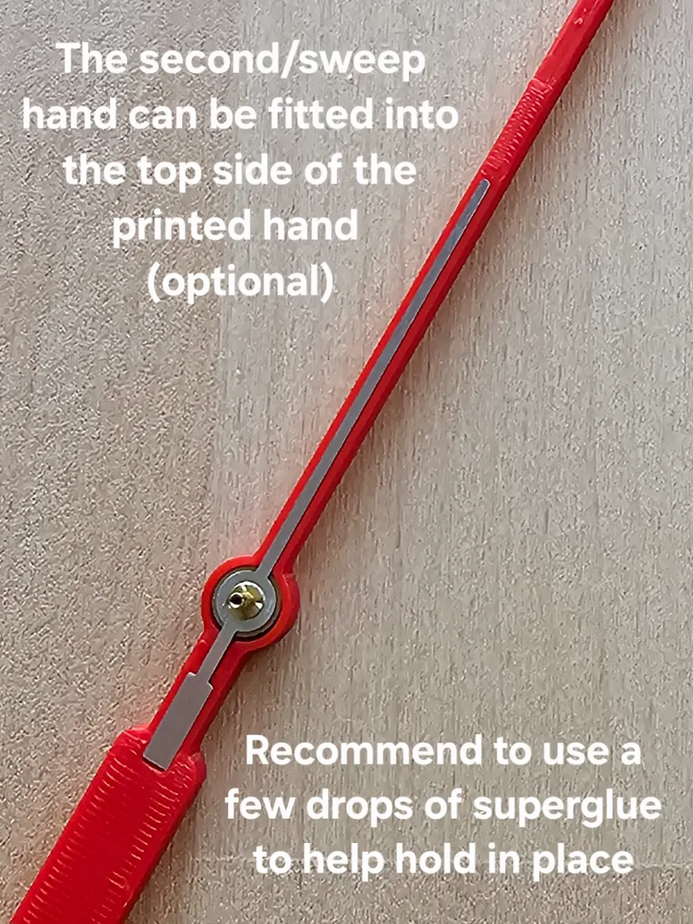
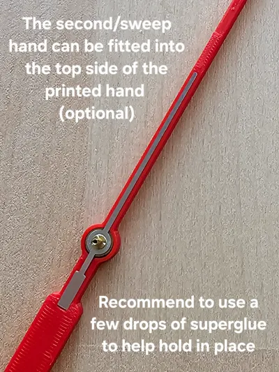
- Optional - place the second/sweep hand from the component kit into the recess on the printed second/sweep hand (suggestion is to add a few drops of super glue to keep it securely in place). My print has been working fine without glue.
Installation
The template and template arm simplify setting up the clock onto the desired surface. I suggest you use the following steps:
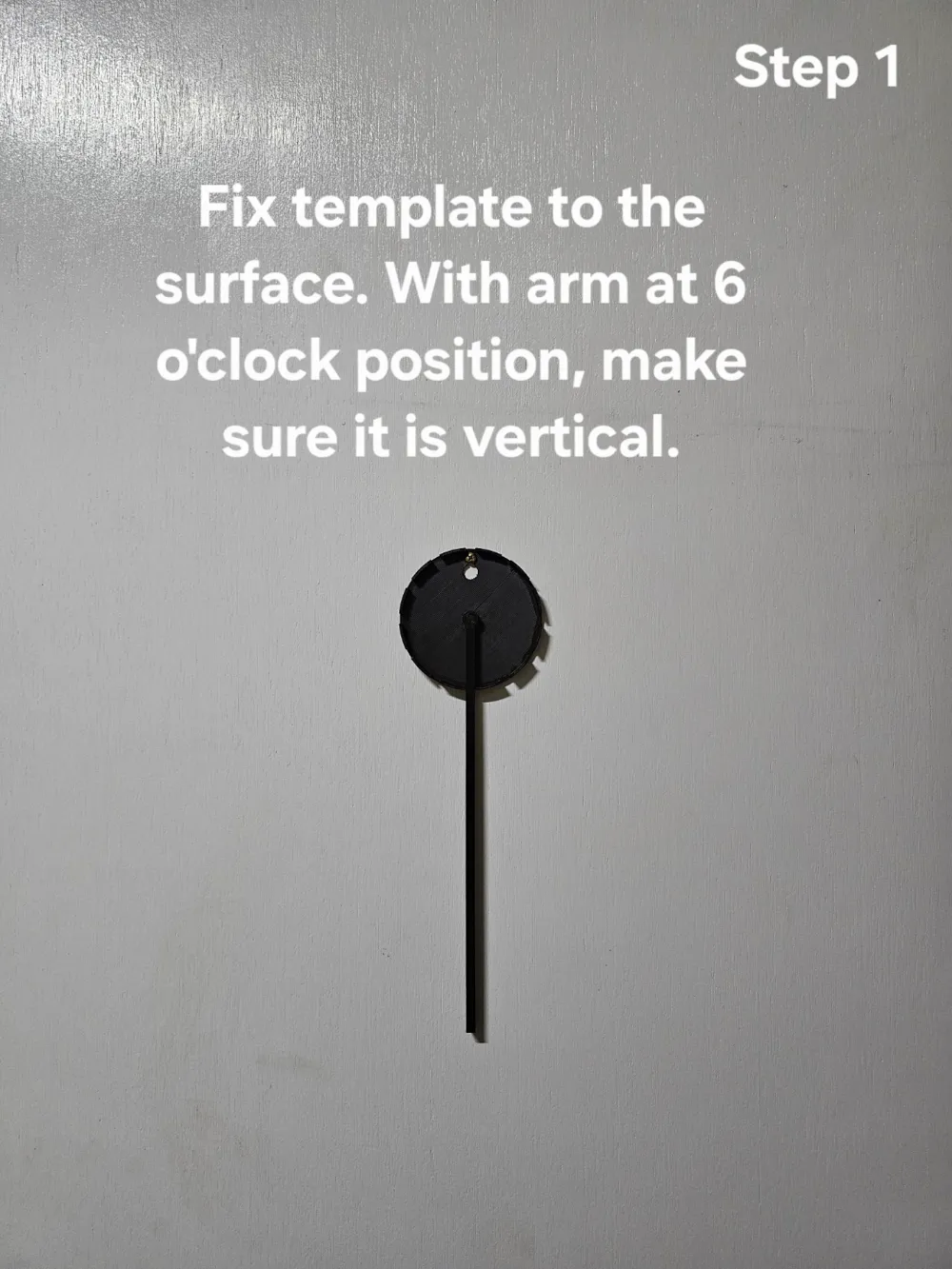
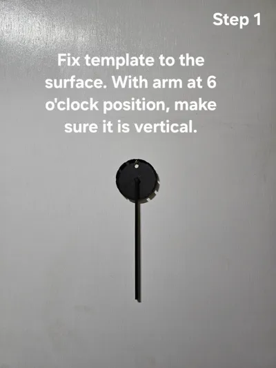
- Position the template at the location for your clock mechanism (main holder). The template and main holder are the same size, with the same mounting position. Add the template arm to the template and have it protrude through the 6 o'clock position (screw fixing point at the 12 o'clock position). Ensure the arm is vertical. Securely fix the screw holding the template (see Step 1 photo).
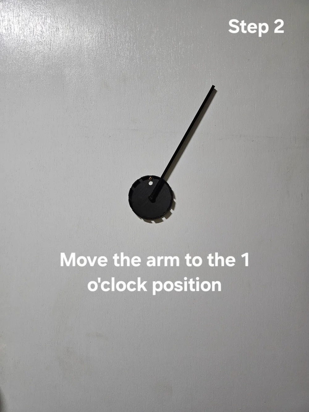
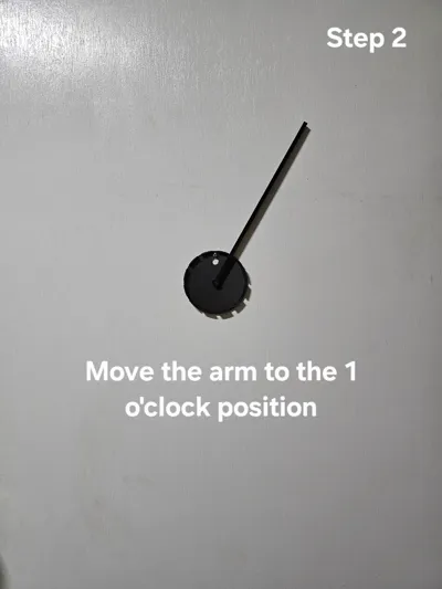
- Move the template arm to the 1 o'clock position (see Step 2 photo).
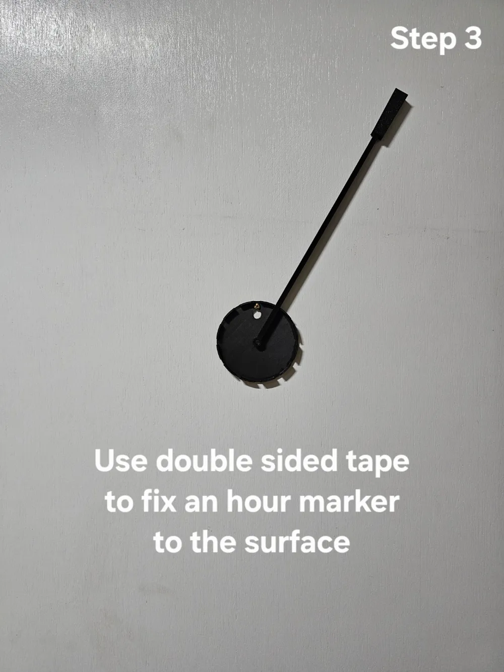
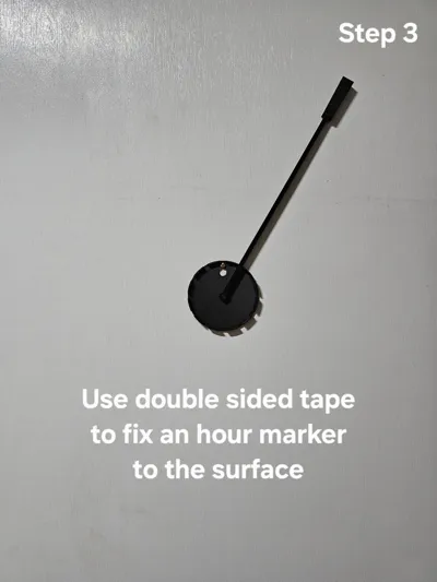
- Use double sided tape to fix one of the hour ticks at the end of the arm (the ticks are wedge shaped). You can either have the gyroid facing out or facing the wall so that the print surface finish is seen (see Step 3 photo).
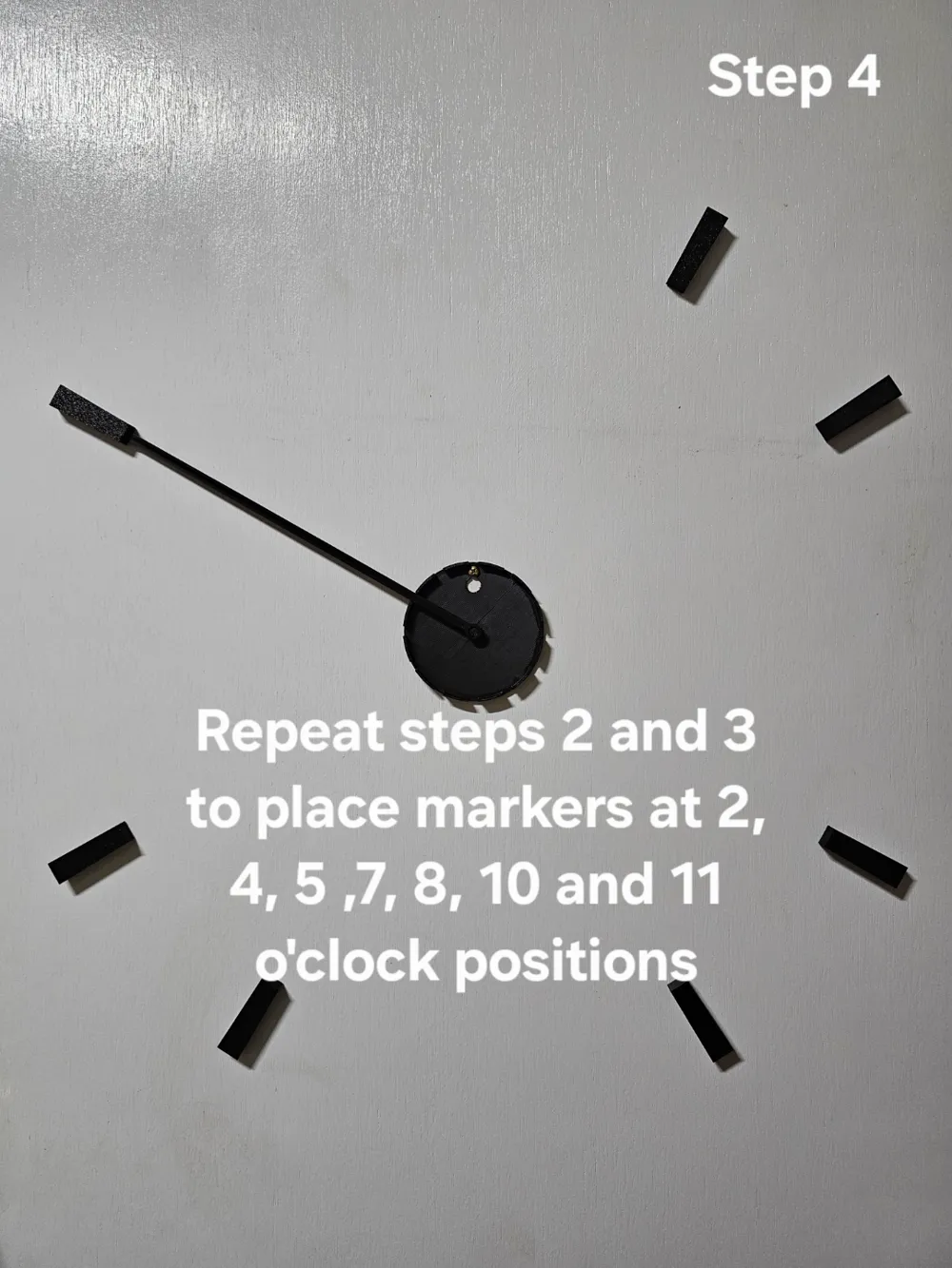
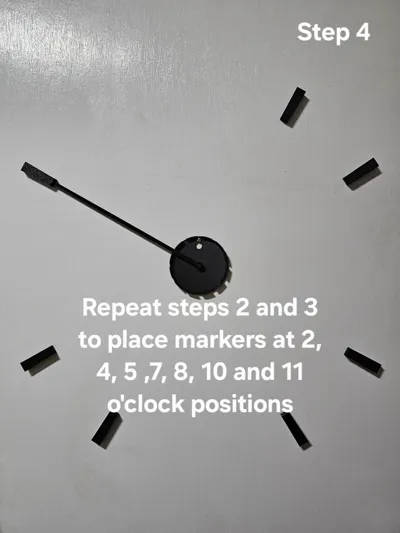
- Repeat steps 2 and 3 so that the hour ticks are added to each of the 2, 4, 5, 7, 8, 10 and 11 o'clock positions (see Step 4 photo).
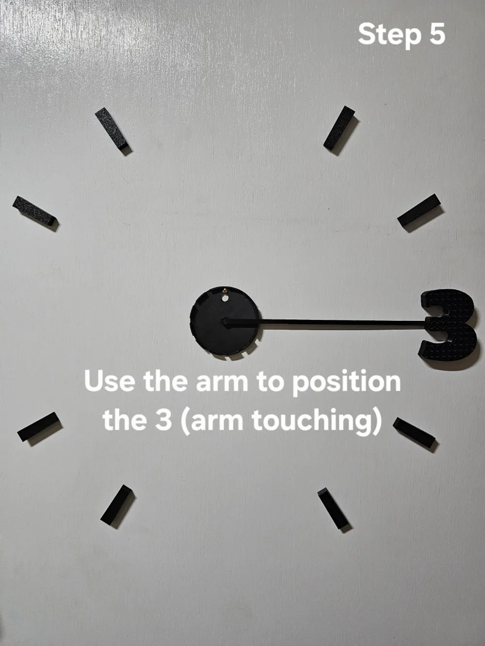
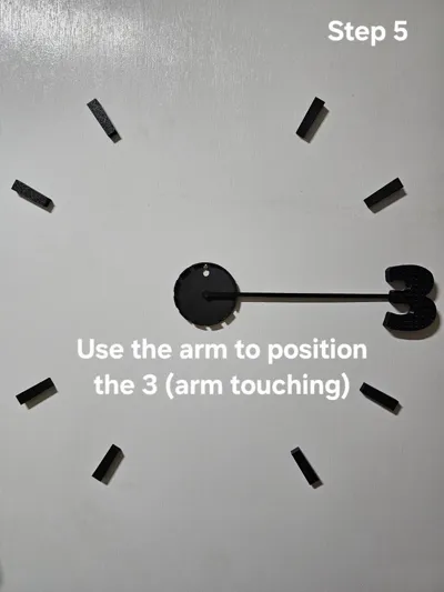
- Move the template arm to the 3 o'clock position and place the large number 3 as seen in the Step 5 photo.
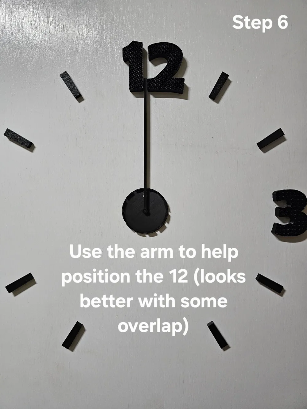
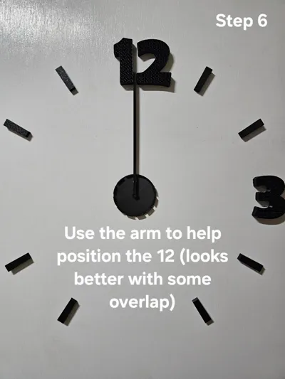
- For the remaining sets of numbers - some overlap will be required. This is easily done at the 12 o'clock position (see Step 6 photo).
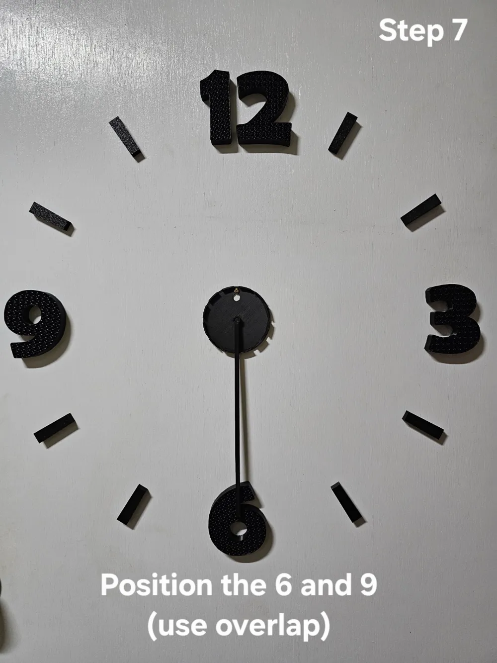
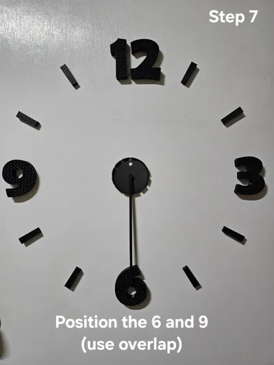
- For the 6 and 9 o'clock positions, I found it simpler to lift the outer end of the template arm and place on top of the numbers (see Step 7 photo).
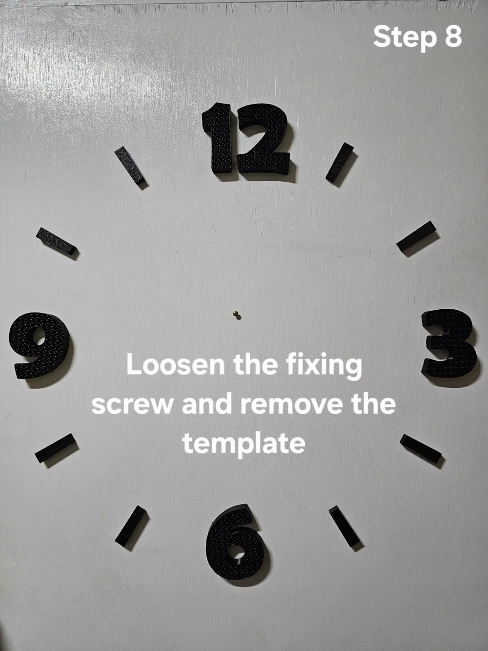
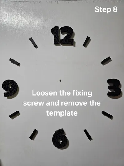
- Loosen the screw holding the template (only far enough so that the template can be lifted up then removed) (see Step 8 photo).
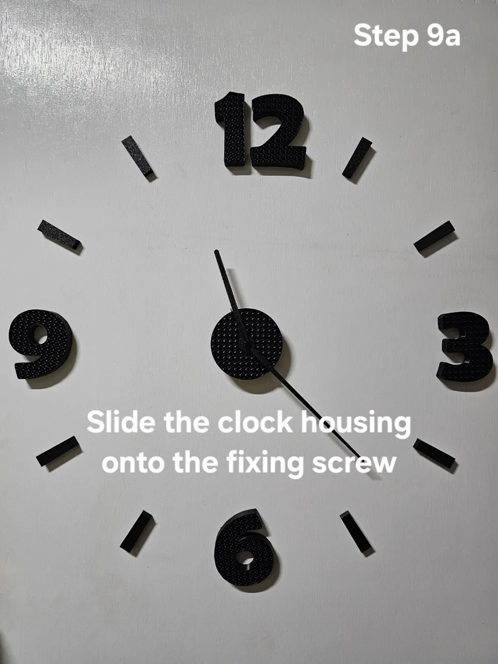
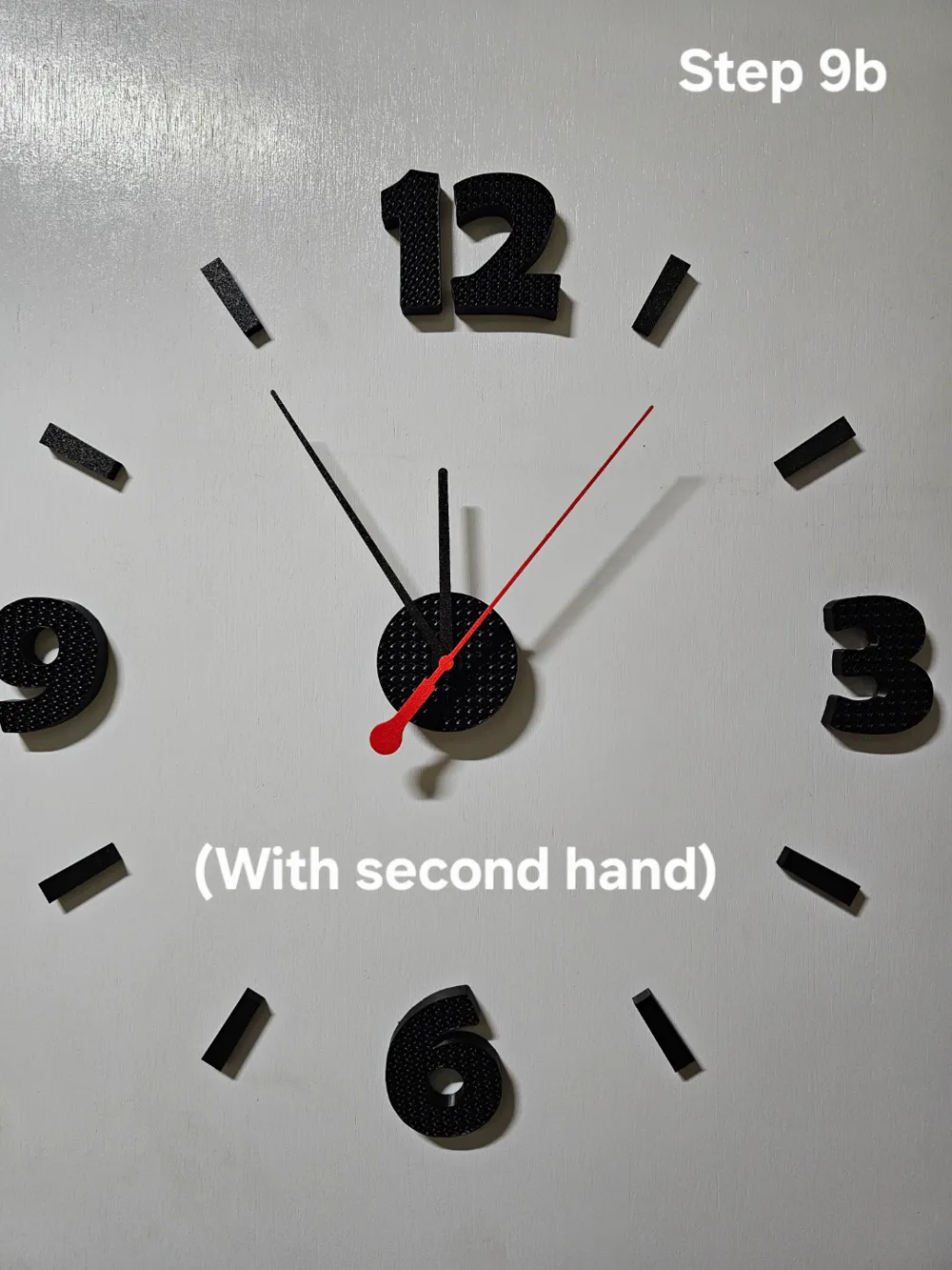
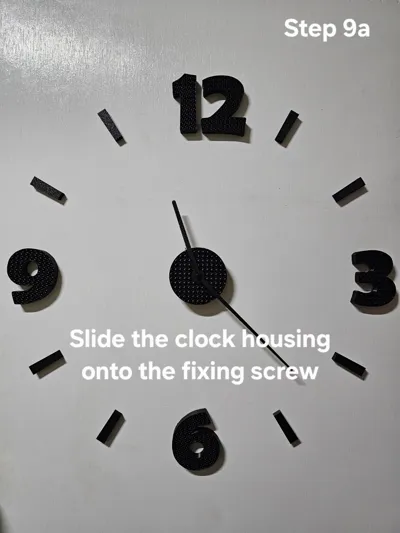
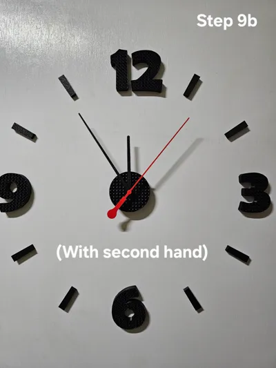
- Insert an AA battery into the clock mechanism and adjust the time. Place the operating clock housing onto the screw used for the template. (see Step 9a/ Step 9b photos).
License



Comment & Rating (2)