
Enclosure Environmental Controller
Print Profile(3)
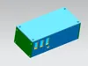
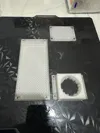
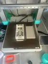
Description
Introduction
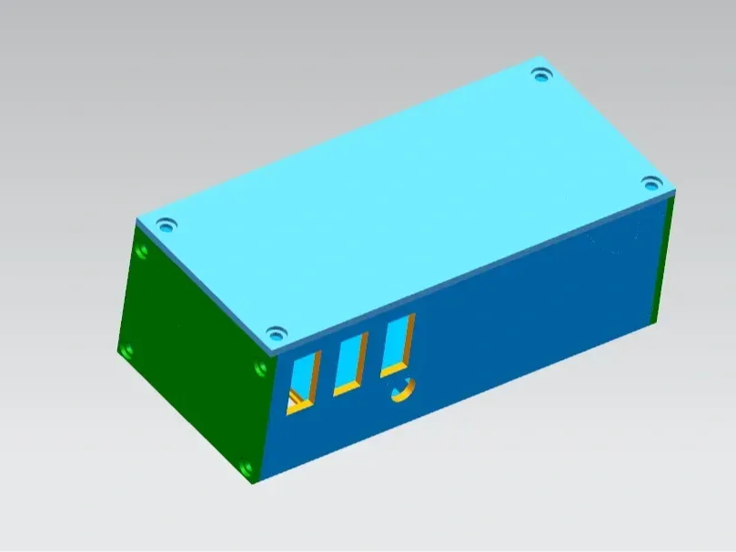
This project aims to create a compact, 3D-printed enclosure environmental control system. Powered by an AMS lite device, it provides internal illumination, thermal management via ventilation, and power monitoring. Controlled via an ESP32 with ESPhome firmware, it utilizes a 12V fan, a 5V RGB LED strip, a BH1750, and a DHT11 to sense environmental factors and actuate accordingly, thereby creating the desired environment. Currently, device control relies on a HASS platform bridged to HomeKit. Due to the substantial power consumption of the PTC, temperature regulation is not yet implemented. Some features remain incomplete; users can expand functionality as needed if a PCB is created or updates are released. Exercise caution regarding electrical safety. This project has broad applicability, offering a streamlined solution for intelligent environmental control.
I. Hardware Preparation
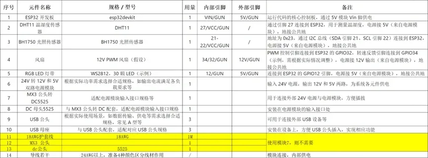
For enhanced component cooling, a 5V 5010 fan with integrated temperature control can be added.
II. Hardware Assembly Steps
- Power Module Connection
- First, securely mount the 24V to 12V and 5V dual-output power module within the enclosure's chassis using a suitable mounting bracket. Connect the external 24V power supply to the module's input port using an MX3 male-to-DC and DC female connector. Ensure correct polarity and secure connections to prevent short circuits.
- Next, connect the power module's 12V output to the fan's power input, and the 5V output to the ESP32's Vin pin and other 5V components (e.g., sensors). Connect all ground pins to the power module's ground pin for a common ground. Use thicker gauge wire for optimal grounding.
- If the 12V and 5V grounds are separate, connect them to create a common ground to ensure proper 12V fan PWM signal transmission.
- The first version uses an AMS lite interface for power, therefore no PTC is included; avoid using high-power devices.
- Sensor Connections
- Connect the DHT11's data pin to a designated ESP32 pin (GPIO27 in this example) using soldering or reliable crimp terminals. Connect the DHT11's power to the 5V output and ground to the common ground (or the 3.3V/GND pin of the development board, depending on the situation).
- For the BH1750, connect SDA to the corresponding ESP32 SDA pin (e.g., pin 21), and SCL to the SCL pin (e.g., pin 22). Connect power to 5V and ground to the common ground (or the 3.3V/GND pin of the development board). Carefully verify pin assignments.
- Actuator (Fan and LED Strip) Connections
- Fan Connection: Connect the fan's PWM control signal USB male connector to the appropriate ESP32 control pin (GPIO32 in this example). Connect the fan's power to the 12V output and ground to the common ground. The speed feedback in this instance corresponds to GPIO34. Mount the fan's matching USB female connector in an accessible location on the enclosure, ensuring proper and secure alignment.
- LED Strip Connection: Connect the RGB LED strip's data input USB male connector to the designated ESP32 control pin (GPIO12 in this example). Connect the LED strip's power to the 5V output and ground to the common ground. Mount the corresponding USB female connector for convenient access.
- USB Male and Female Connector Installation (Including Reserve Power and Other Expansions)
- USB Male Connector for Camera Power: Connect it to the 5V output and common ground of the power module. Install the corresponding USB female connector in an easily accessible location on the enclosure. Ensure proper pin alignment for the camera's USB power cable. Consider connecting the LED strip control pin (GPIO12 in this example) for shared or interchangeable use.
III. Debugging Steps
- Initial Inspection
- After assembly, carefully inspect all connections for loose wires, short circuits, or poor connections. Pay close attention to USB connector pin alignment and secure connections.
- Power Testing
- Connect the external 24V power supply. Use a multimeter to verify the 12V and 5V outputs, and check for proper voltage at all components (ESP32, sensors, fan, LED strip). Investigate any anomalies, ensuring connections and wiring are sound. Verify the 5V output and ground for the reserved camera power USB connector.
- Sensor Functional Testing
- Observe the DHT11 and BH1750 for proper operation; check indicator lights (if applicable) or use professional testing equipment for accurate output verification. If readings are incorrect, check ESP32 connections and sensor integrity. Replace sensors if necessary.
- Actuator Functional Testing (Fan and LED Strip)
- Fan Testing: Connect the fan via USB, and test varying control signals (via manual code or existing interface, if any) to observe speed adjustments. If there's a speed feedback line, examine the data accuracy. Address any issues with wiring, ESP32 settings, or fan malfunctions.
- LED Strip Testing: Connect the RGB LED strip via USB, and send test commands to check lighting effects (color changes, brightness). Investigate connection, power, and strip integrity for any anomalies.
- Reserved USB Power Functionality Testing (for Camera)
- Connect a 5V test device (e.g., a small USB-powered LED, simulating a camera) to verify power functionality. Investigate any power supply issues with the USB connector and power module.
- Integrated System Testing
- After individual component testing, conduct integrated system testing. Simulate real-world conditions (temperature, humidity, light) and observe the system's response (fan speed, lighting). Investigate any inconsistencies in signal transmission, control logic, etc. Repeat multiple times with plug-and-play USB connections to ensure consistent functionality.
Future Developments
This device currently lacks buttons, local automation, MQTT, and HomeKit support. All control is via HASS, bridged to HomeKit. Further updates are unlikely (unless a PCB is developed). Add desired functionality through the configuration file; exercise extreme caution with electrical safety.
Documentation (1)
License

You shall not share, sub-license, sell, rent, host, transfer, or distribute in any way the digital or 3D printed versions of this object, nor any other derivative work of this object in its digital or physical format (including - but not limited to - remixes of this object, and hosting on other digital platforms). The objects may not be used without permission in any way whatsoever in which you charge money, or collect fees.


Comment & Rating (0)