
DECCA tree
Print Profile(1)

Description
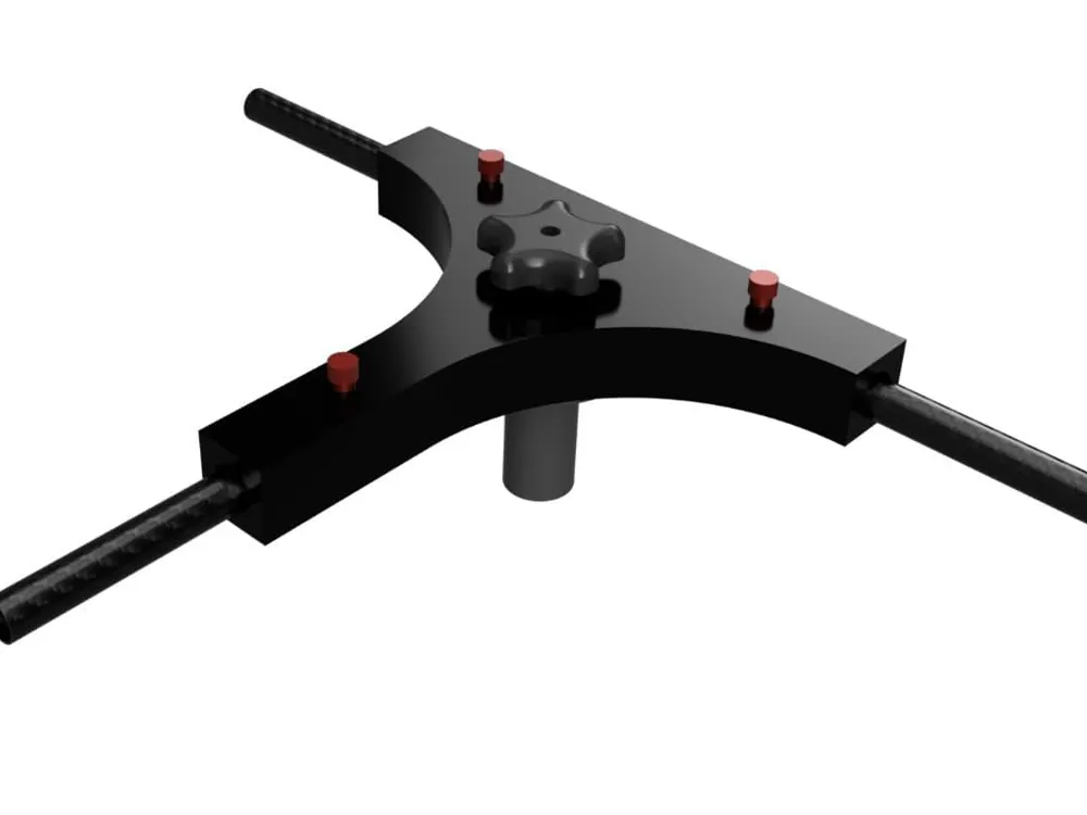
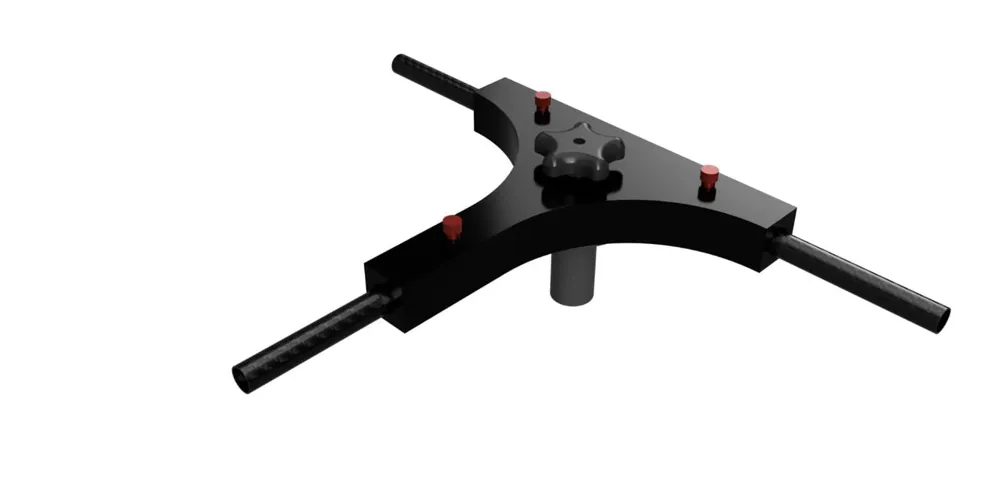
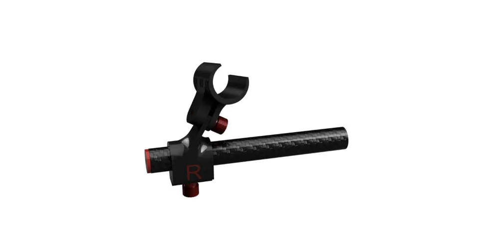
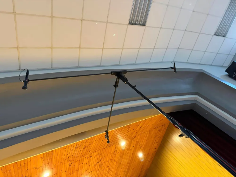
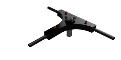
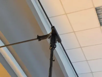
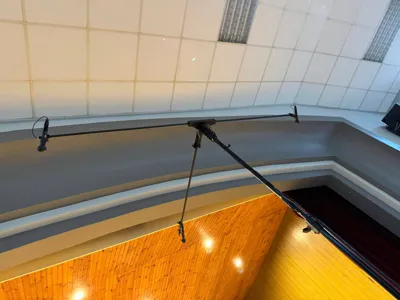
The DECCA tree is a microphone setup which has 3 microphones in a triangle above the conductor before the orchestra. Setups are complicated and expensive, while this 3D printed version is very light and uses some commercially of the shelve components (screws, inserts and carbon fiber tubing). It is the ultimate low cost DECCA tree, using Neumann KM183 and their spheres.
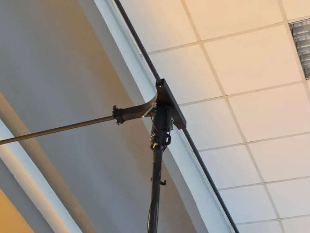
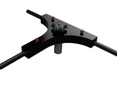
The setup is designed to put on top of a lighting or speaker stand. As it is very light, any stand will do. I am using a Manfrotto 269HDBU, because it can be used for high setups as well. The center is designed to use the Manfrotto type 14, but you will need a metal convertor and a knob to mount it to the stand. This could also be 3D printed, but I had one lying around of metal which I liked more. You could use something like this: https://www.thomann.de/nl/manfrotto_163_38_28mm_tv_spigot.htm
I have printed all parts in ABS+ (black, white, red and green). ABS+ is tough, but a little bit flexible so it allows for nice clicking when put together and when the microphones are clicked in place. I have printed a couple of them and take them with me, just in case one of them breaks at the location.
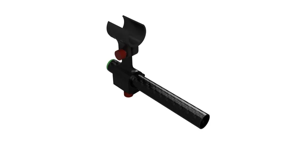
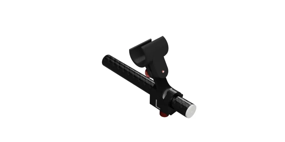
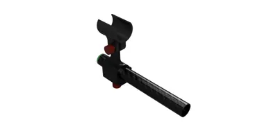
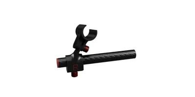
The clamps all have a hinge which is printed in place. This allows the clamp to be removed, even with the cables inside the tubing.
A lot of parts use 3mm inserts which are melted into place. You can buy them from Amazon, for instance: https://amzn.eu/d/gsrX8CP
To fasten the tubes and clamps, I used 3mm thumb screws, which can be found here: https://amzn.eu/d/haJHIZF
And of course you will need to source the carbon fiber tubes. They should be 1m long with an outer diameter of 15mm and inside either 13mm or 12mm. The 12mm will be more stiff, but the 13mm will work just fine.
You will also need microphone cables, that are thin. They will be passed the endstop. I have used Sommer Cicada SO-D14, which is only 2.6mm thick and can be sourced here: https://www.thomann.de/nl/sommer_cicada_sod14_sw.htm. In theory, you could lead this cable all the way to your recorder/interface, but that is a little messy. So I used mini-XLR just below the central mounting point to go to a regular multi core which is then going to the interface. The mini-XLR click neatly to the transport clip.
Assembly
Insert the M3 inserts to all the holes.
Insert the tubes into the central mounting triangle.
Lead the cables through the end stops, through the tubes, through the mounting triangle.
Solder the XLR connectors on both ends.
Storage
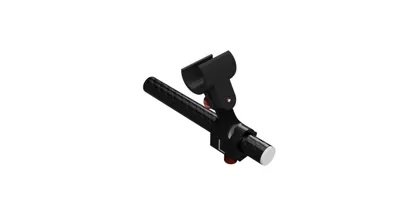
When not in use, the MID tube stays in place, while the L and R tubes are removed from their central mounting point (cable is still inside). Then the L R tubes are clicked on top on the MID tube, using the the storage clips. The storage clips can stay in place during recordings as they are barely visible. When setting up for the recording, just do it the other way around…
License

You shall not share, sub-license, sell, rent, host, transfer, or distribute in any way the digital or 3D printed versions of this object, nor any other derivative work of this object in its digital or physical format (including - but not limited to - remixes of this object, and hosting on other digital platforms). The objects may not be used without permission in any way whatsoever in which you charge money, or collect fees.


Comment & Rating (3)