
Hidden Compartment Clock
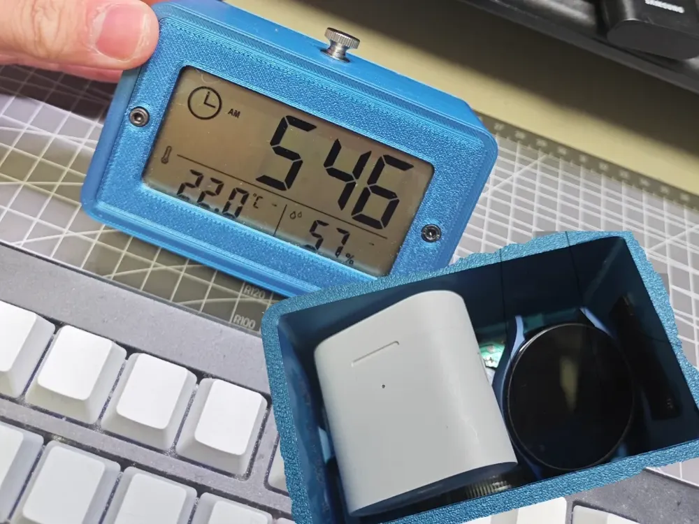
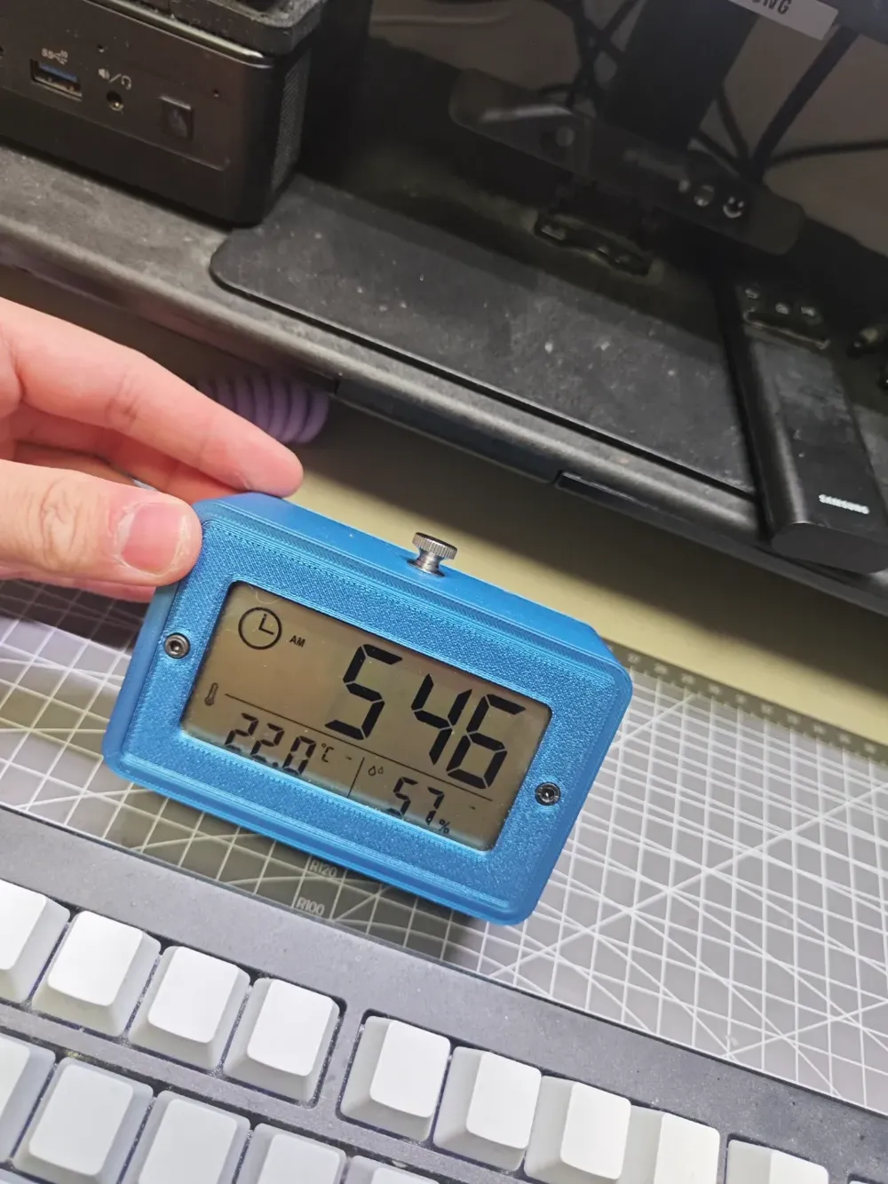
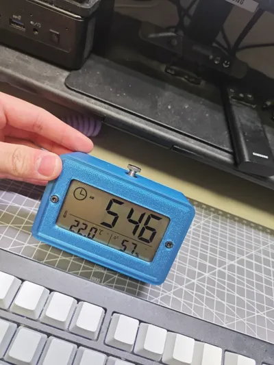
Print Profile(1)
Description
A hidden compartment clock, relatively difficult to assemble (requires a soldering iron and soldering skills). I will design a simpler version if possible.
Demonstration video: None available
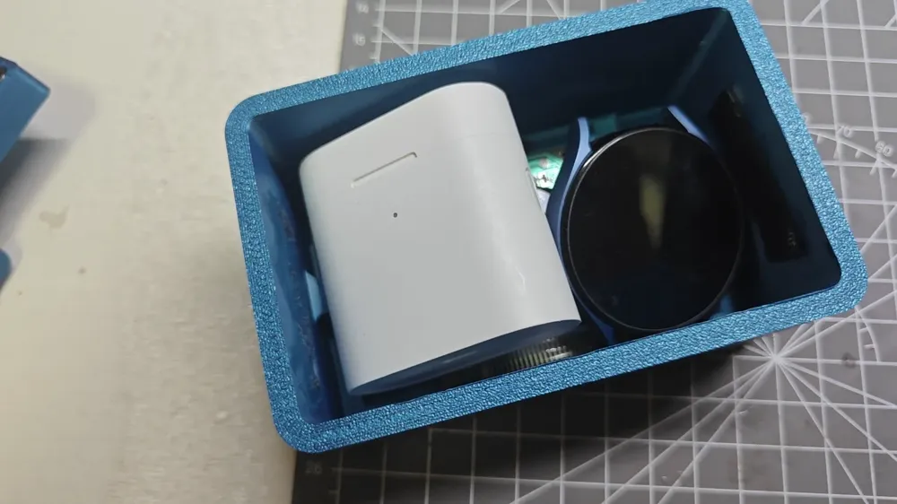
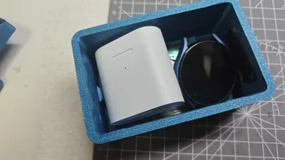
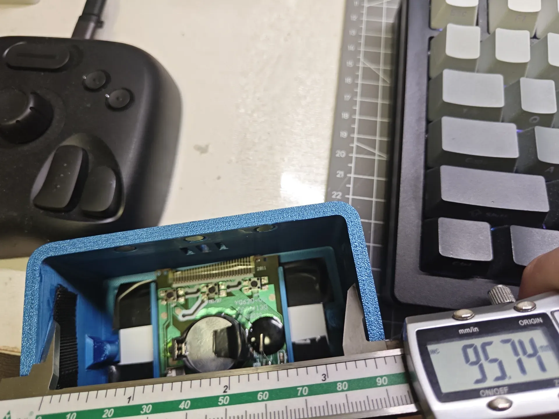
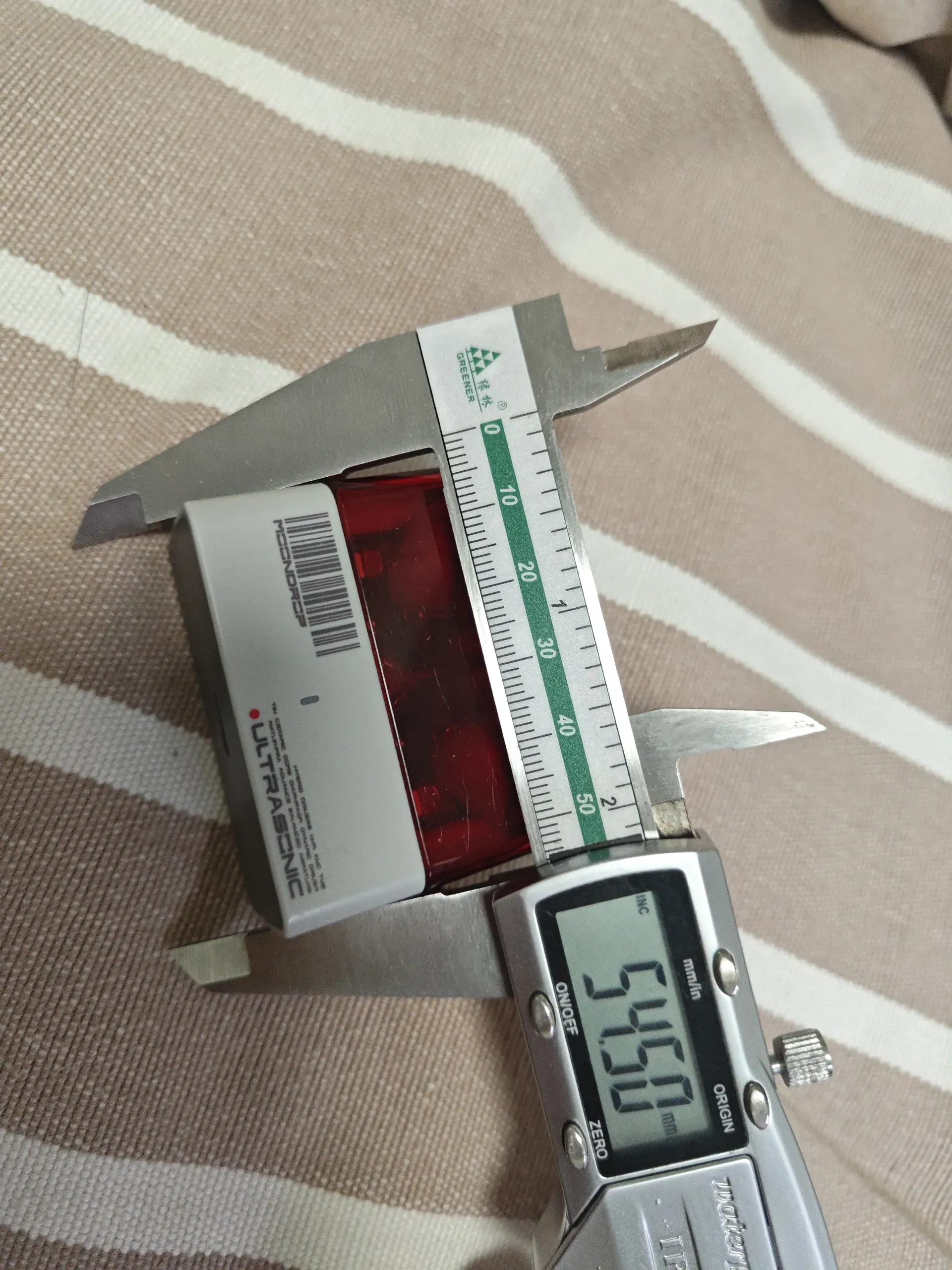
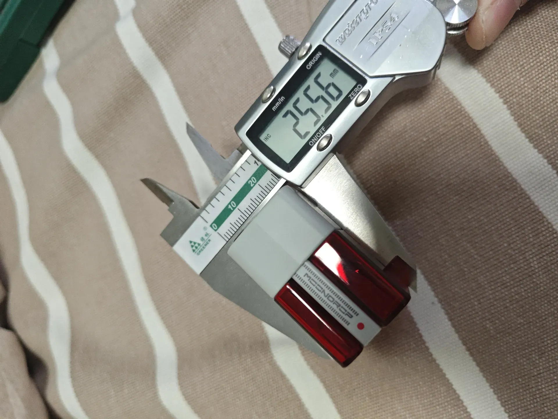
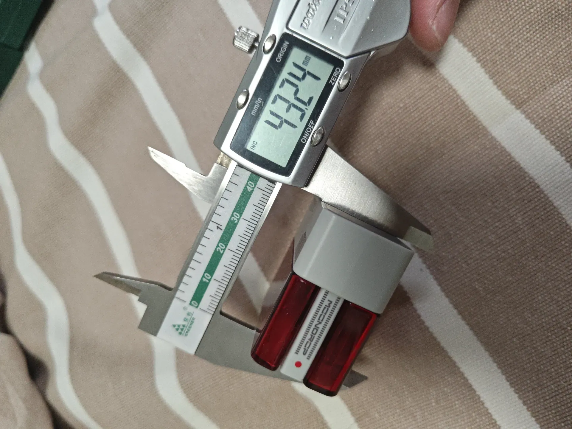
Testing shows it can hold a Galaxy Watch 5 (without the strap) and a Xiaomi Air2s headset. Similar sized items and the Shuiyueyu ultrasonic device can also fit inside.
Dimension diagram shown below
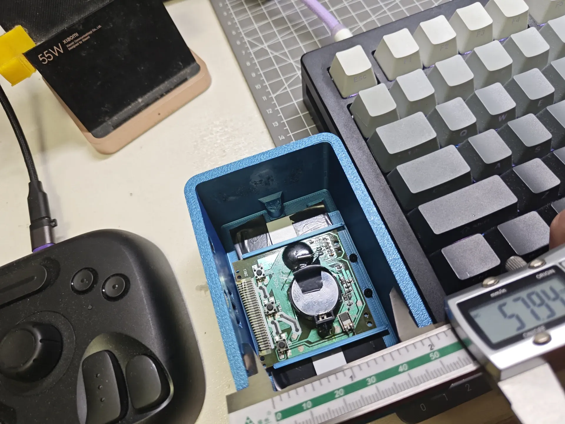
Headset dimensions
Materials:
- 3D printing filament, no specific requirements
- 6 x M3x8 cup head screws
- 1 x M3x10 hand-tightening screw
- 3 x 3x4x5 heat-melt nuts (M3 thread, 4mm height, 5mm outer diameter; use a soldering iron to press them into the printed parts)
- 2 x M2x5 self-tapping round head screws
- 6 x 6x3mm magnets (3mm thick, 6mm diameter)
- Button cell battery holder CR2032 3V button cell battery holder, direct plug,
- Clock (purchased and disassembled) Color options: Temperature and humidity clock (white with battery included)Desktop Clock, Mini Temperature and Humidity Meter, Digital Electronic Time Display - tmall.com (Added 2024/11/23, valid at the time, future availability not guaranteed)
Assembly
1. Press in the heat-melt nuts and glue the magnets:
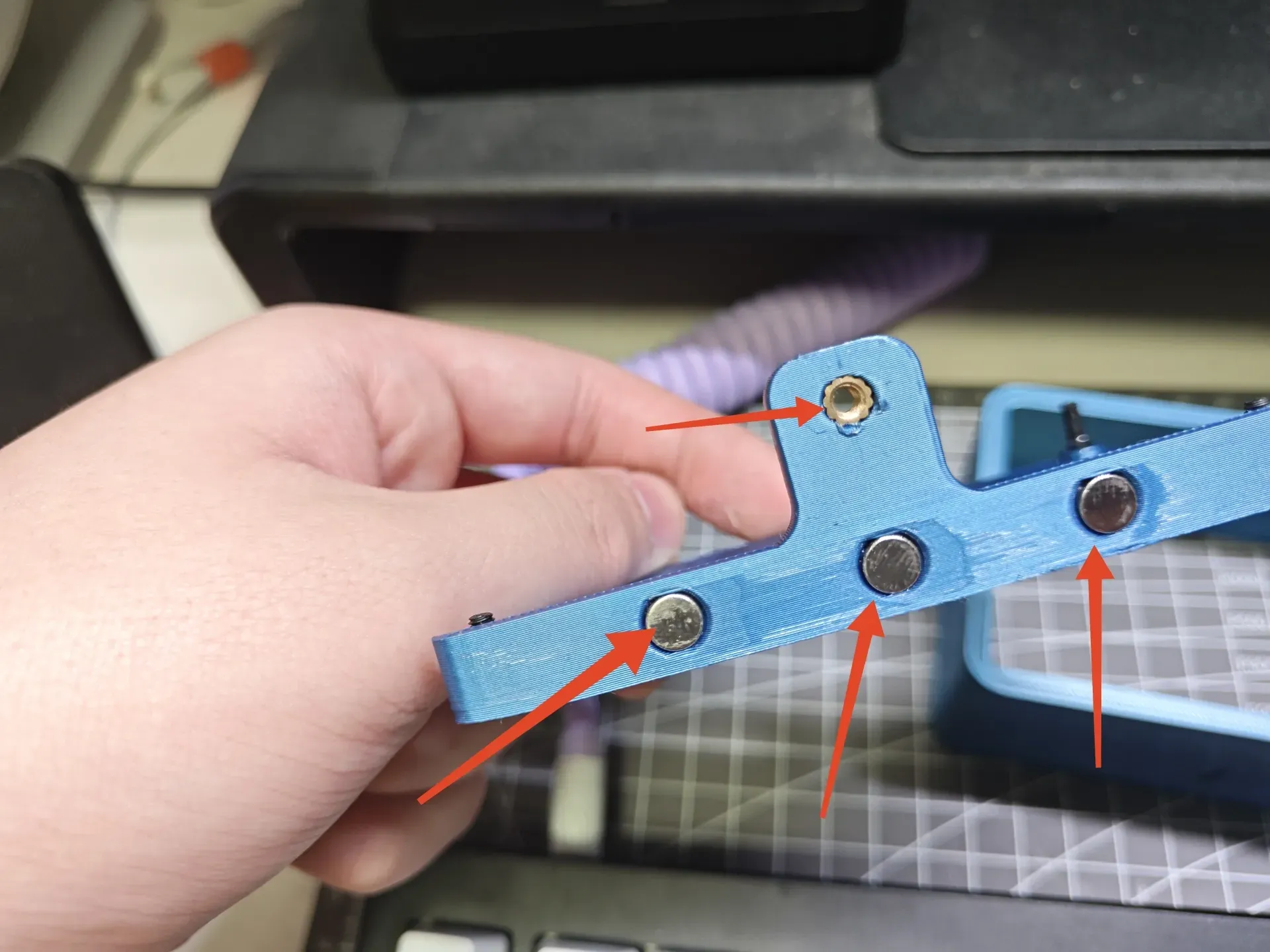
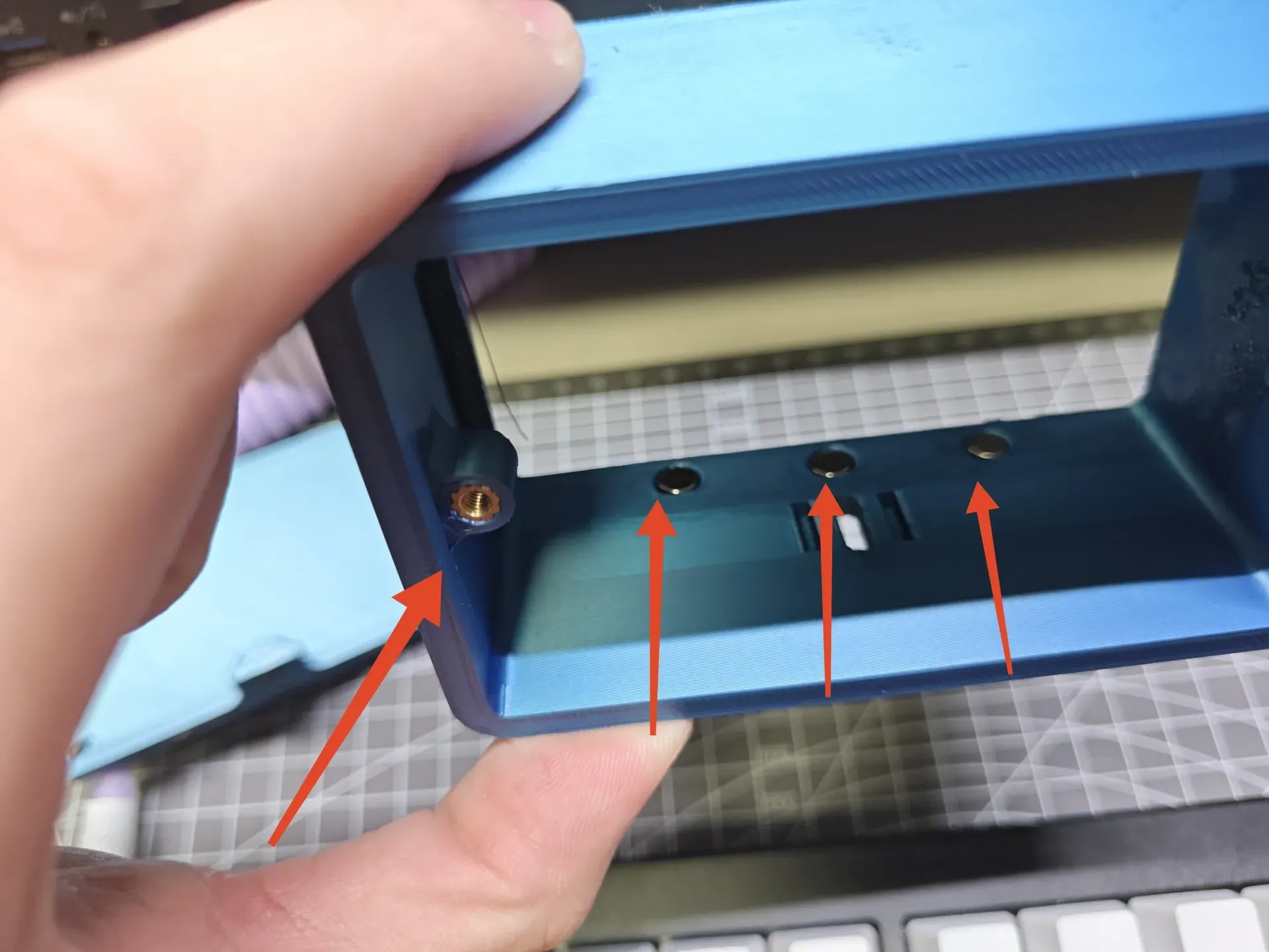
The arrows indicate where the heat-melt nuts need to be pressed in/magnets glued.
Place the back cover onto the case. The six magnets will attract each other pairwise; pay attention to the orientation!
PS: The second image is incomplete. It's symmetrical; the nuts on the right side also need to be pressed in.
Caution: Be careful not to burn yourself when pressing in the nuts!!!
2. Disassemble the clock and solder the button cell battery holder to the clock's mainboard.
First, place the clock into the front cover, referring to the previous diagrams.
See diagram below.
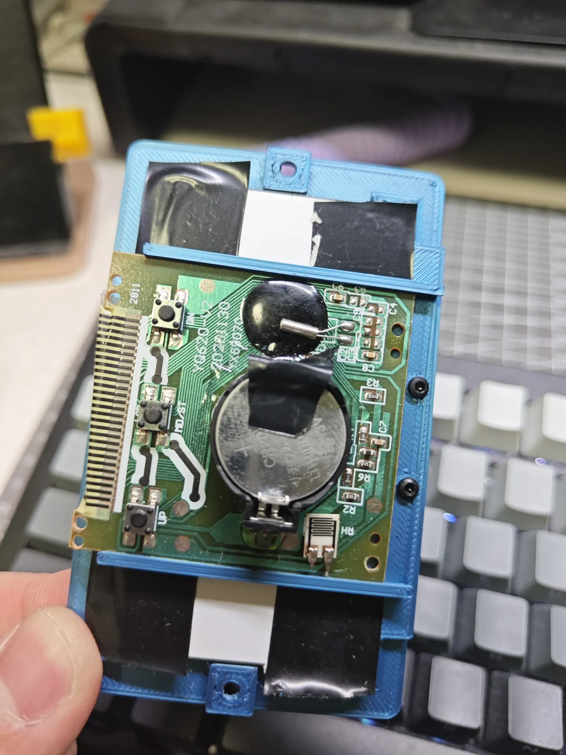
Then, insert the mainboard into the pcb-bracket.stl and fasten it to the front cover using M2x5 self-tapping screws.
3. Install the dummy screws on the back cover; simply use glue to attach them since they are not functional.
4. Connect the front cover to the case using M3x8 screws.
5. The back cover should automatically adhere to the case due to the magnets; then tighten the hand-tightening screw.
6. All done!
To use, loosen the hand-tightening screw and push towards the back cover. The back cover will slide out, allowing you to insert your hand into the gap to remove the contents before reassembling.
License



Comment & Rating (0)