
Tapo C120 Camera Wall Wart Mount v1.1
Print Profile(1)

Description
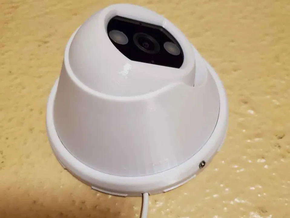
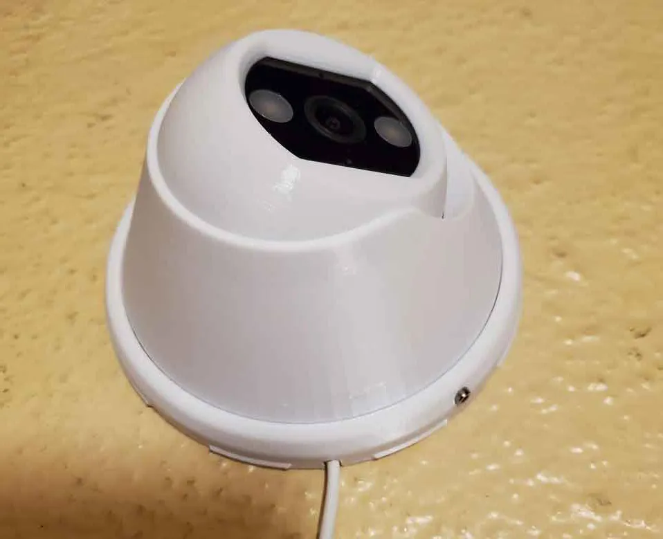
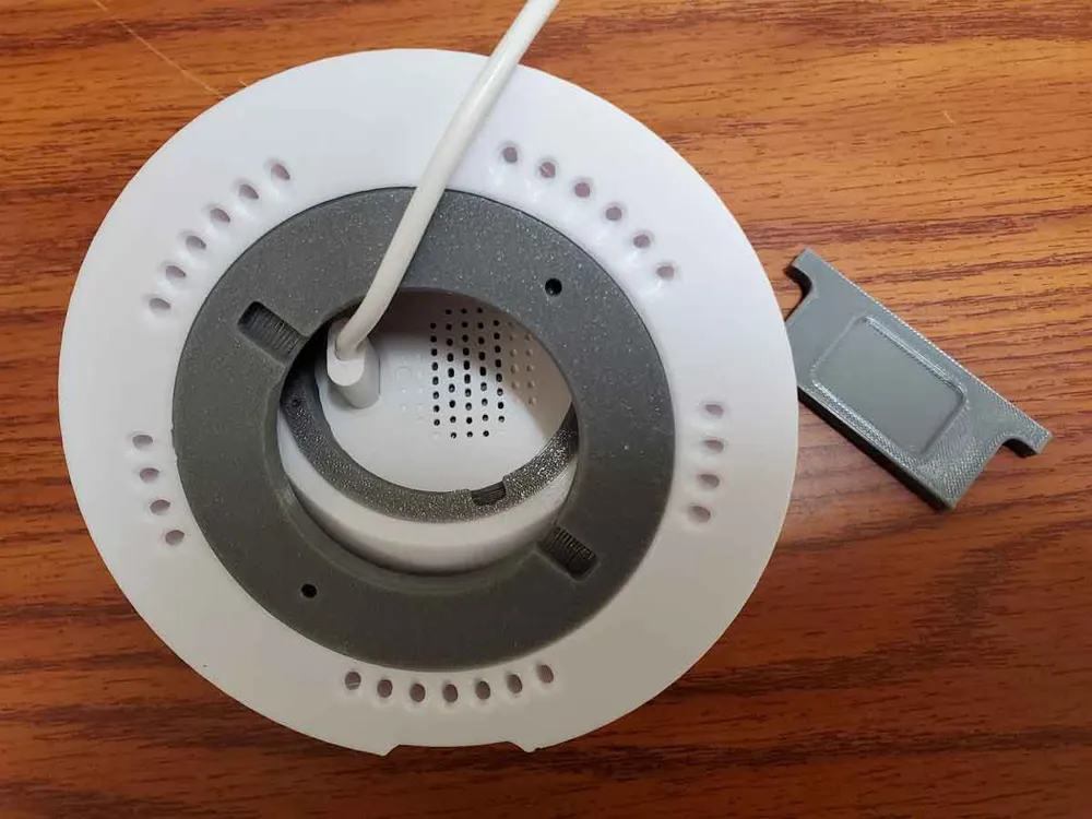
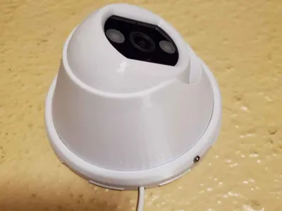
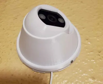
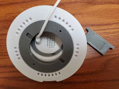
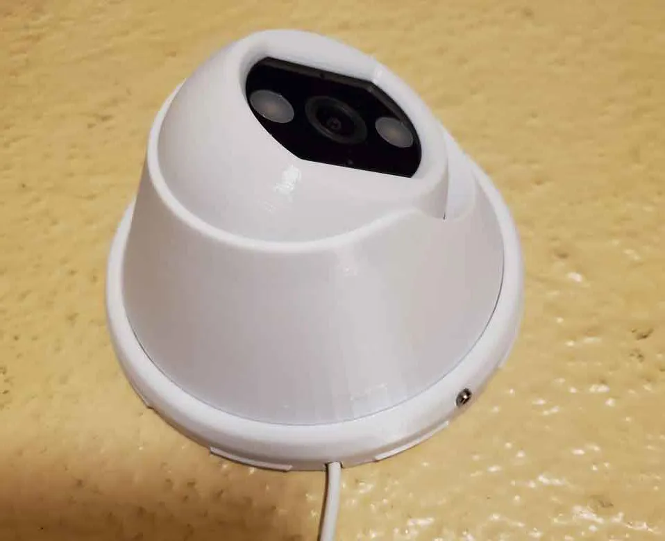
This is a “wall wart” style mount for a Tapo C120 camera. These cameras offer a good bang for the buck, but the stock magnetic mount seems a bit lightweight. I needed to mount several of them outside, and felt the need for a more robust mounting setup, so I made this mo
unt.
 |  |  |
I did my best to design this, and feedback is welcome, but if you make or use this, it is at your own risk.
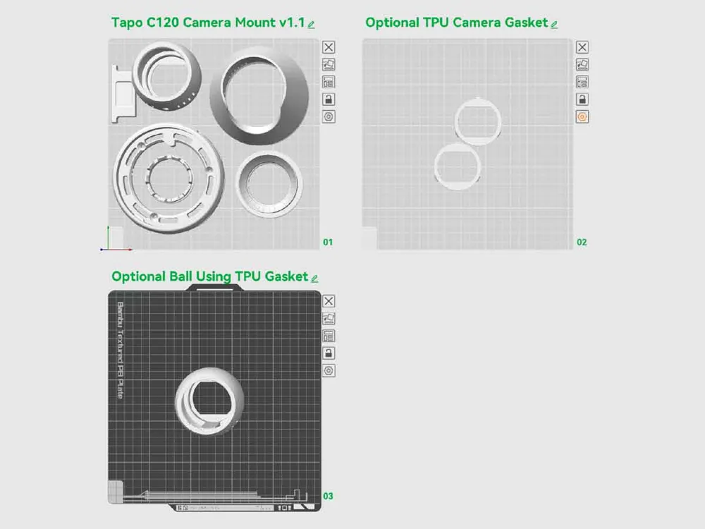
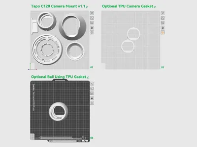
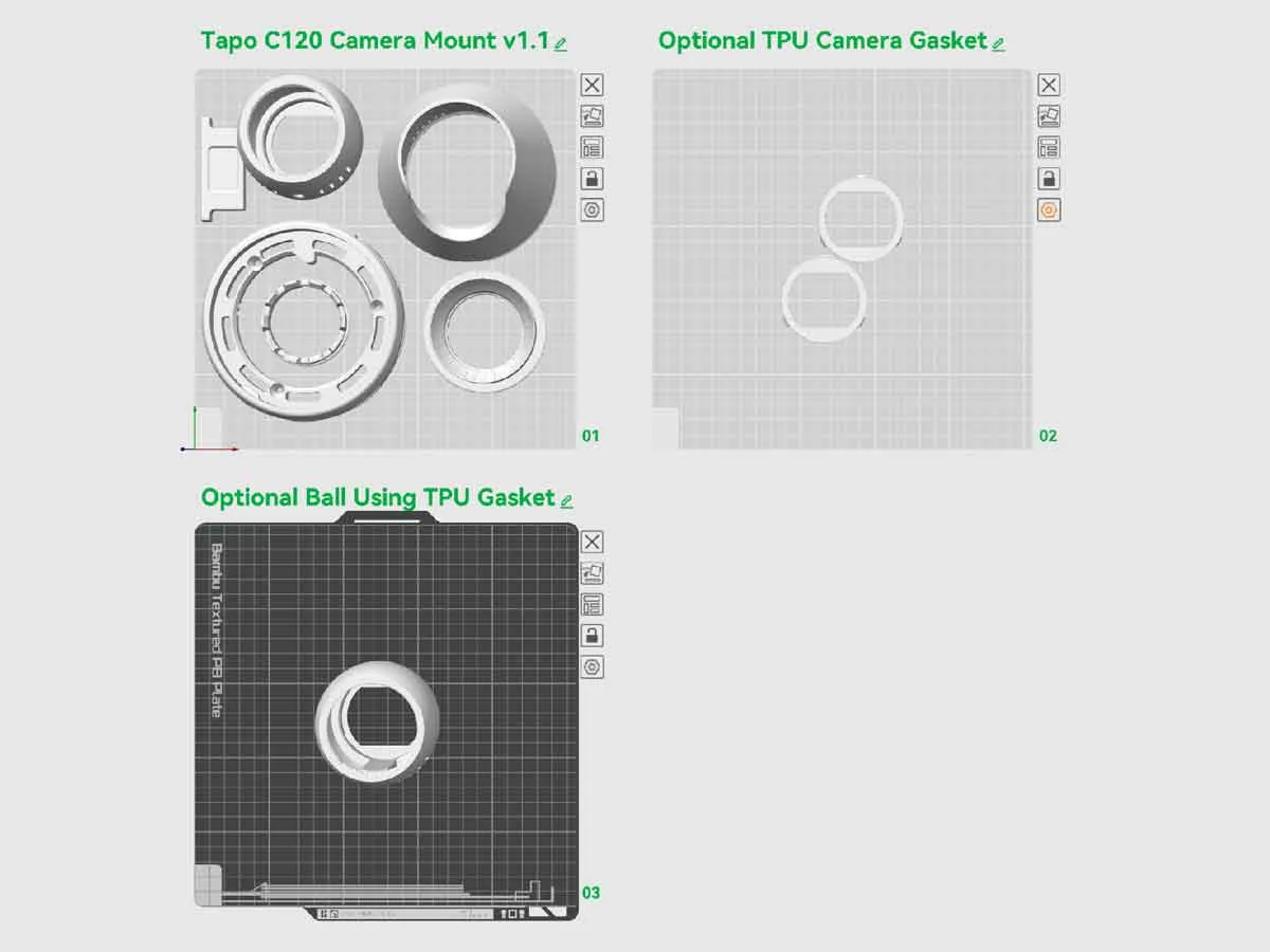
I've included a 3mf with 3 plates, which uses PETG and TPU (optional) for the parts. The STL's are also included for those who want to set up their own plates.
The TPU is used for an optional gasket, which may help keep water from entering the mount from the front, though the mount is not designed to be water resistant. If using the TPU gasket, you will need to print the “ball” file named “TAPO-CAM_mount_v26_BALL_w_GASKET.stl”, which is on it's own plate.
This was designed with some drain holes in the mount, which need to be poked out when the orientation of the mount is finalized. These may help drain any water which makes it's way into the mount. The camera itself has anIP66 weatherproof rating, so my hope was to just to give water a path out of the mount, so it could dry out if it gets wet. I've been using one of these mounts outdoors for over a year now without issues, but it has not tested it really wet or icy conditions, so feedback is welcome.
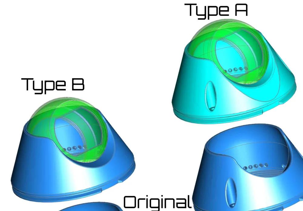
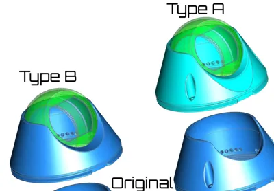
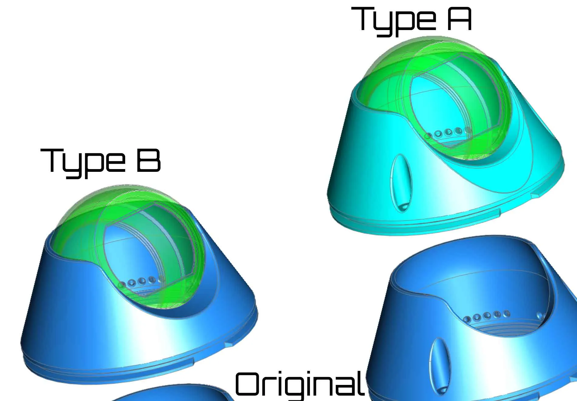
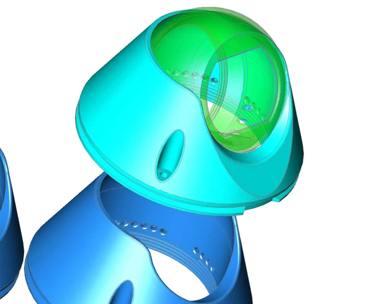
Thanks to feedback, there are two new covers. These are the "TAPO-CAM_mount_v34_COVER_typeA.stl" and "TAPO-CAM_mount_v34_COVER_typeB.stl" files, which can be found in the included v34 profile. These covers are referred to "type A" and “type B”. They can be helpful, if the camera needs to be mounted at a low angle to the mount (see pic below), since they have deeper cutouts which help reduce IR reflections in certain orientations of the camera in the mount. If the camera will be positioned facing outward from the base of the mount (almost perpendicular), then the original mount will work fine.
Please take note of the following:
- Make sure the USB-C cable does not get bent, twisted or pinched during the installation. At extreme angles between the ball and mount, it may not be possible to install the USB-C cable, or it may be bent too much, if that is the case, don't use this mount, or look for an alternative position where the camera can be aimed without stressing the cable.
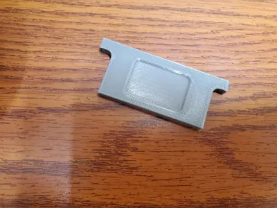
- There are knock-outs on the base for drainage and the optional USB-C cable passthrough which need to be removed and cleaned up before mounting. Make sure there are no sharp edges if using these knockouts, especially on the the USB-cable pass through (if that is used).
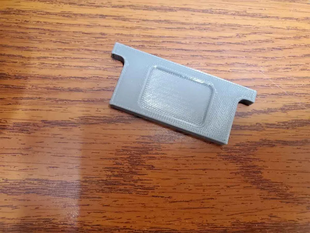
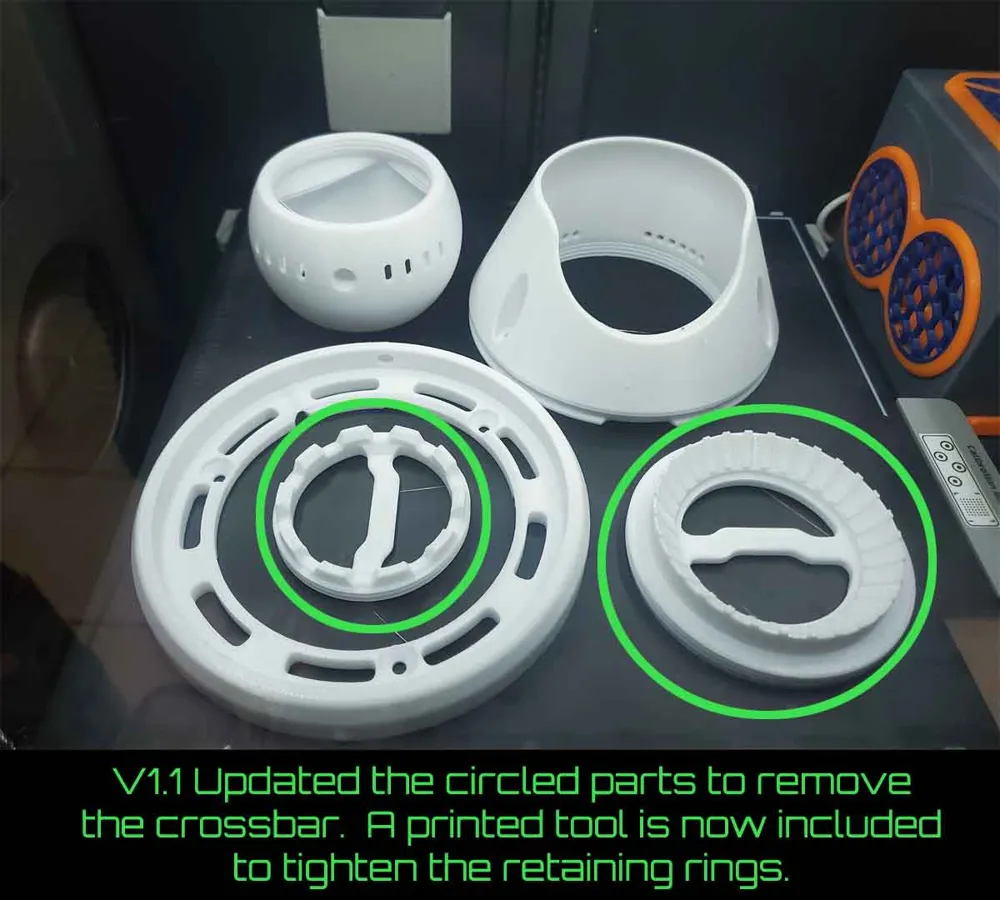
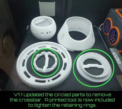
- The retaining rings have been updated, so now the printed tool to is used to tighten them. Don't over tighten the retaining ring for the camera.
- If you have a question or idea to improve this, please post it in the comments.
Assembly:
- To install the mount, first the original mount needs to be removed from the C120 camera. That requires a T6 torx and a small Philips screwdriver. It is also a good idea to install a microSD card and go through the camera setup if it is new at this point, since doing so later will mean disassembly of the mount.
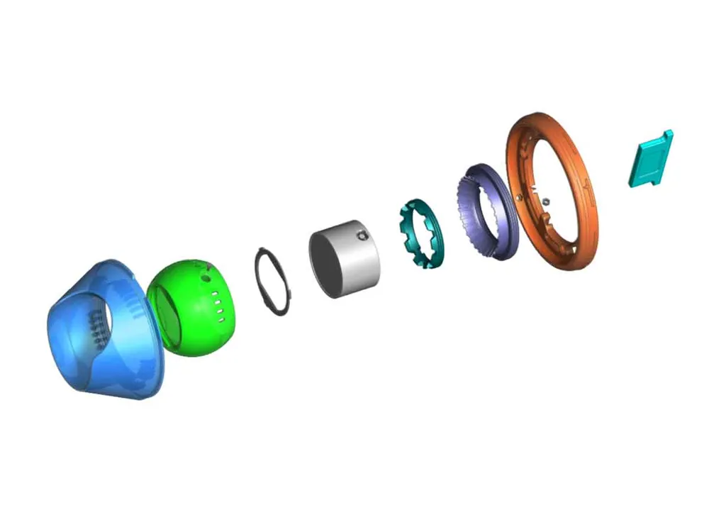
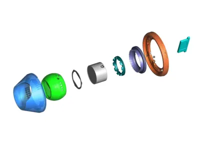
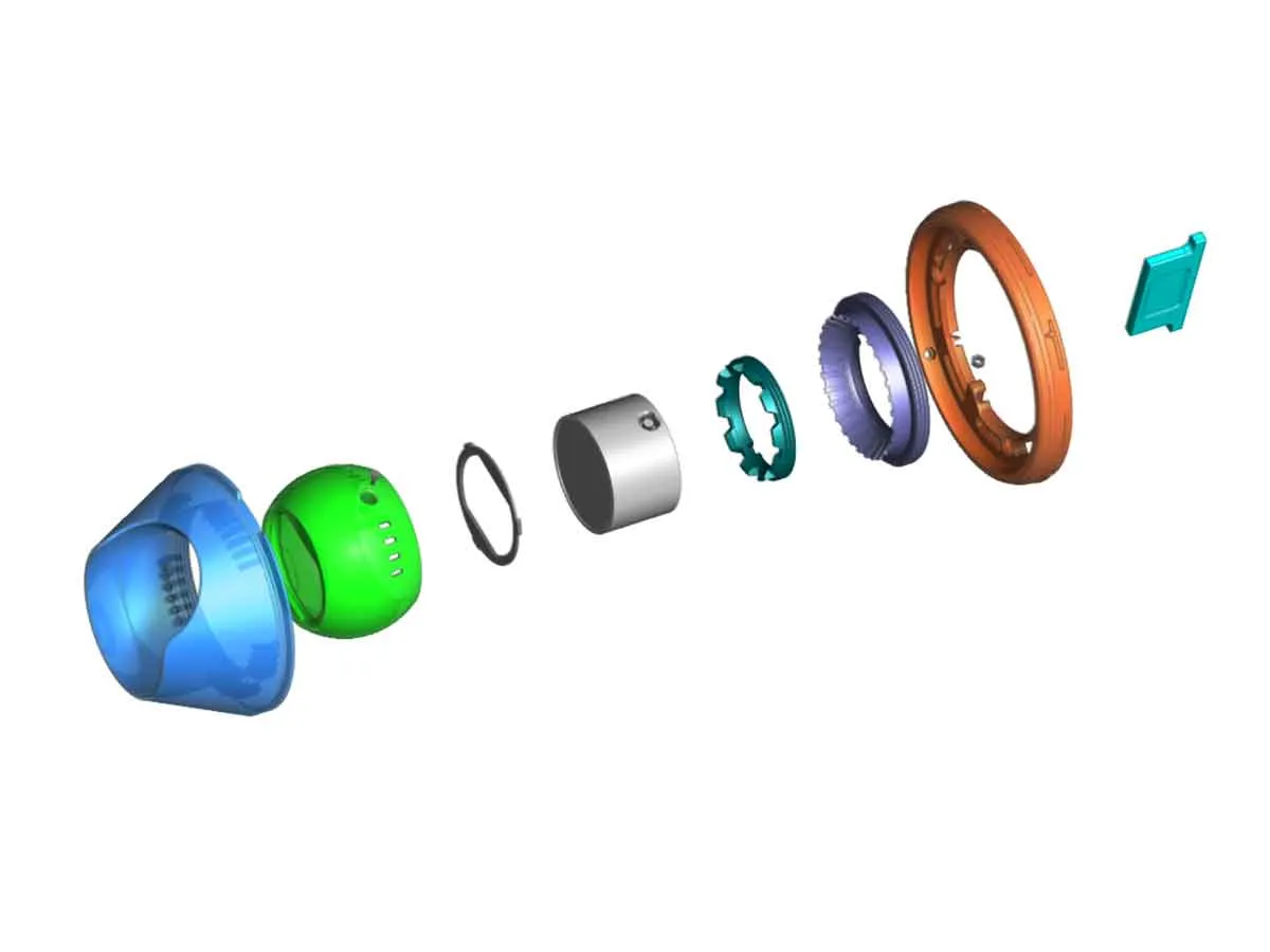
- Make sure to keep the screws. Once the original mounting arm is removed, if using the TPU gasket version of the ball, install the gasket, and then the camera. The gasket has three tabs which will index it into the mount (to use the gasket, the part named “TAPO-CAM_mount_v26_BALL_w_GASKET.stl” must be used as well).
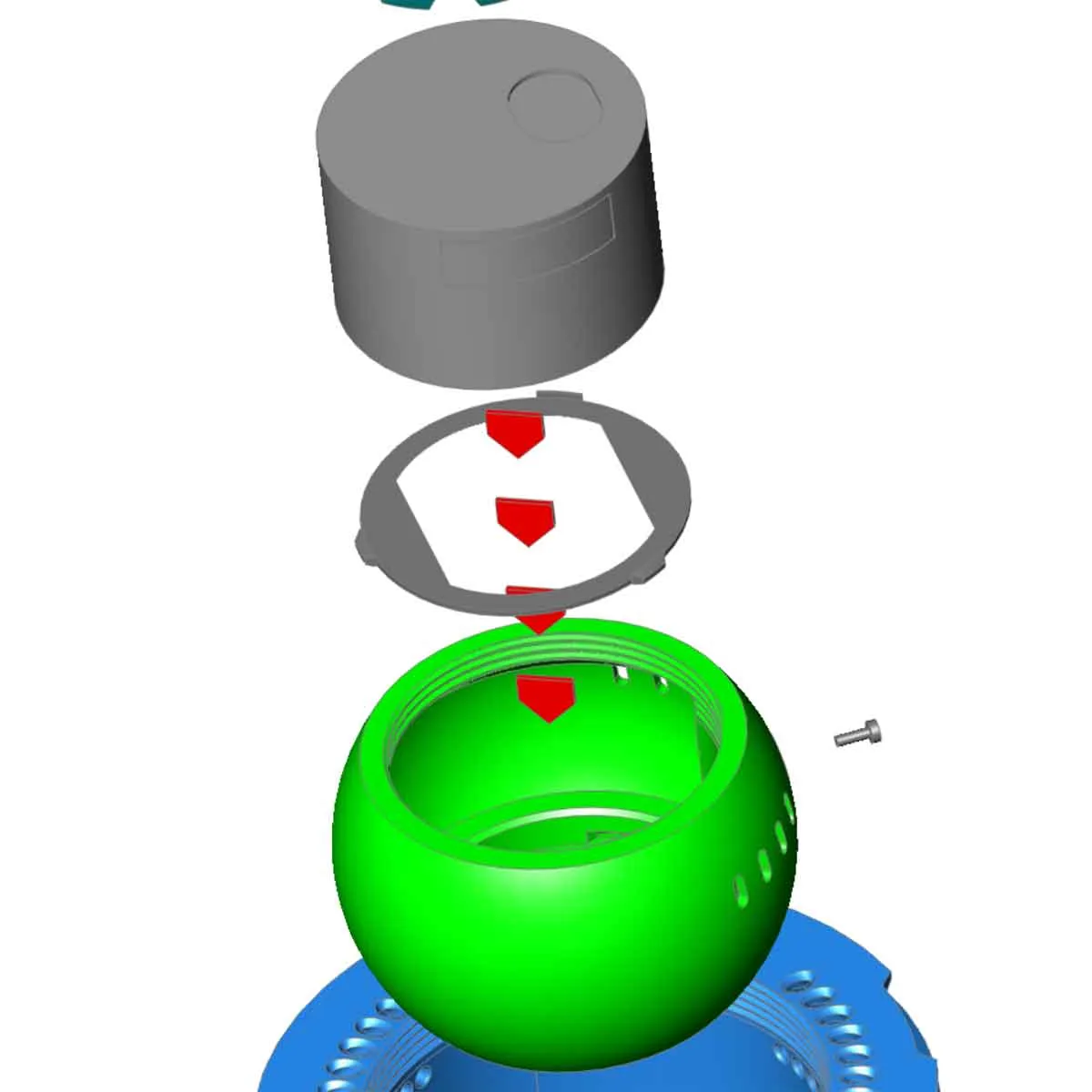
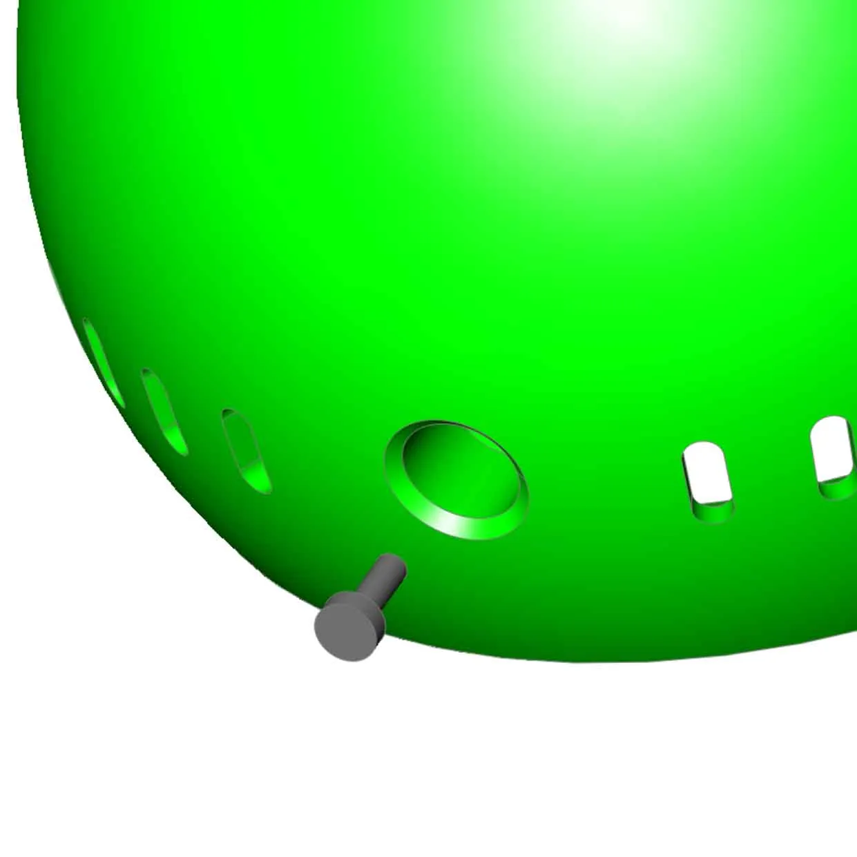
- Align the hole in the ball with the original mounting hole where the small Philips screw was removed earlier and install the screw. The screw will hold the camera in position.
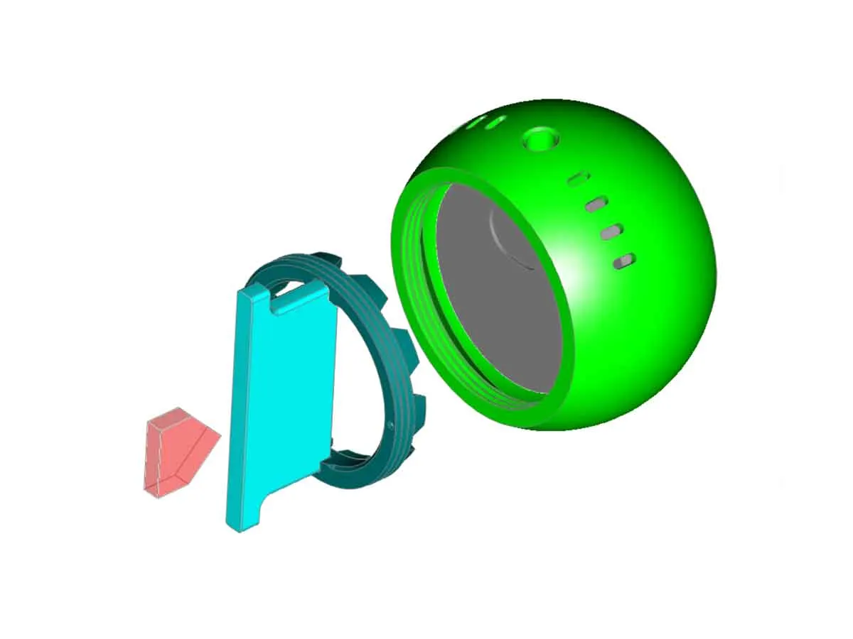
Next install the camera retainer in the ball, by screwing it in using the tool. Do not over-tighten, it just needs to be snug.
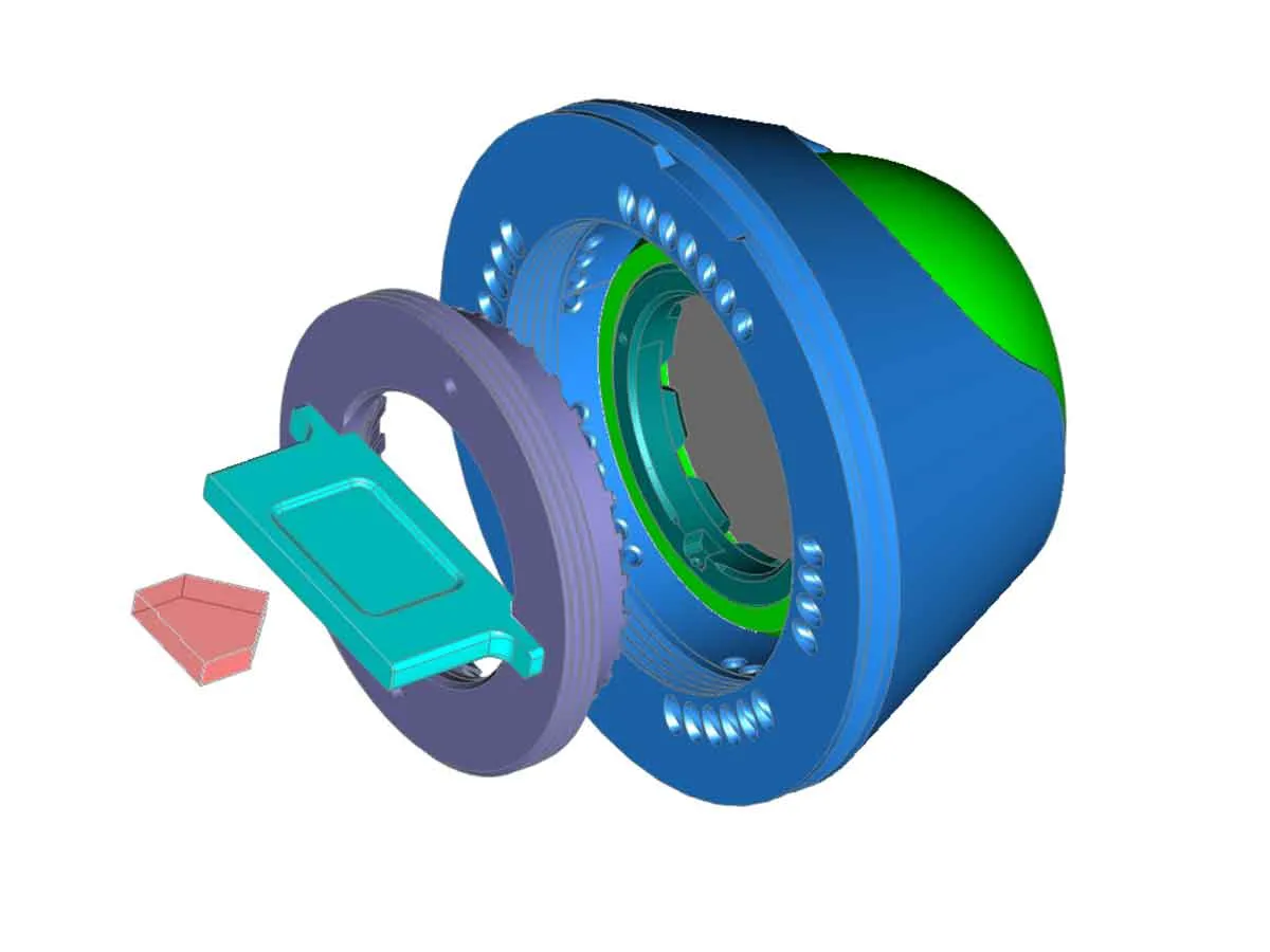
- Install the ball into the cover and make sure it moves around. You can roughly position it to where the camera should aim at this time.
Install the ball retainer in the cover by screwing it in place using the tool, but don't over tighten. The ball should be movable by hand still.
- Install an M3 nut in the base This can be done easier by installing the M3x8 screw through the hole in the base, and then threading the nut on the screw first. Then just pull the M3x8 screw out to seat the nut (may require a pliers). The nut should be flush with the inside edge of the base when done. The M3x8 screw can remain threaded slightly into the nut for now.
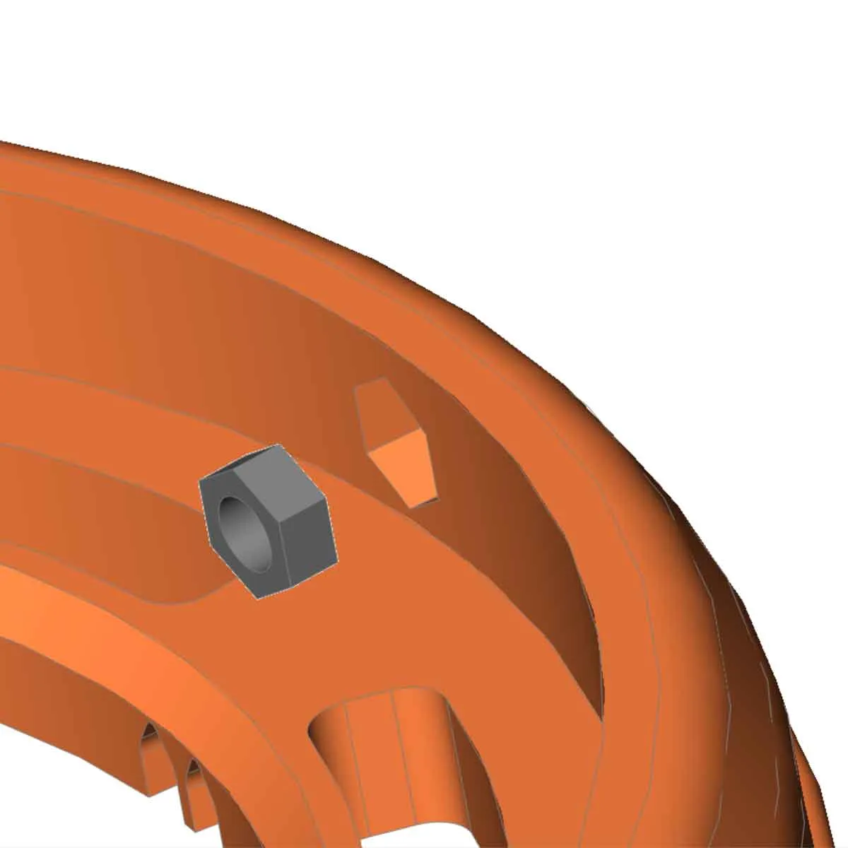
- Take note of the positions of the drain holes and the USB-C cable path on the base of the mount. If the USB-C cable must run through the base of the mount, the hole for the cable will need to be opened up first. To do that, a side cutter and a small round file can be used to remove the necessary knock-outs on the base, before mounting. Some of the drainage knockouts which will be at the bottom of the mount should be removed to allow water to drain. Make sure there are no sharp edges where the USB-C cable will pass through the base of the mount.
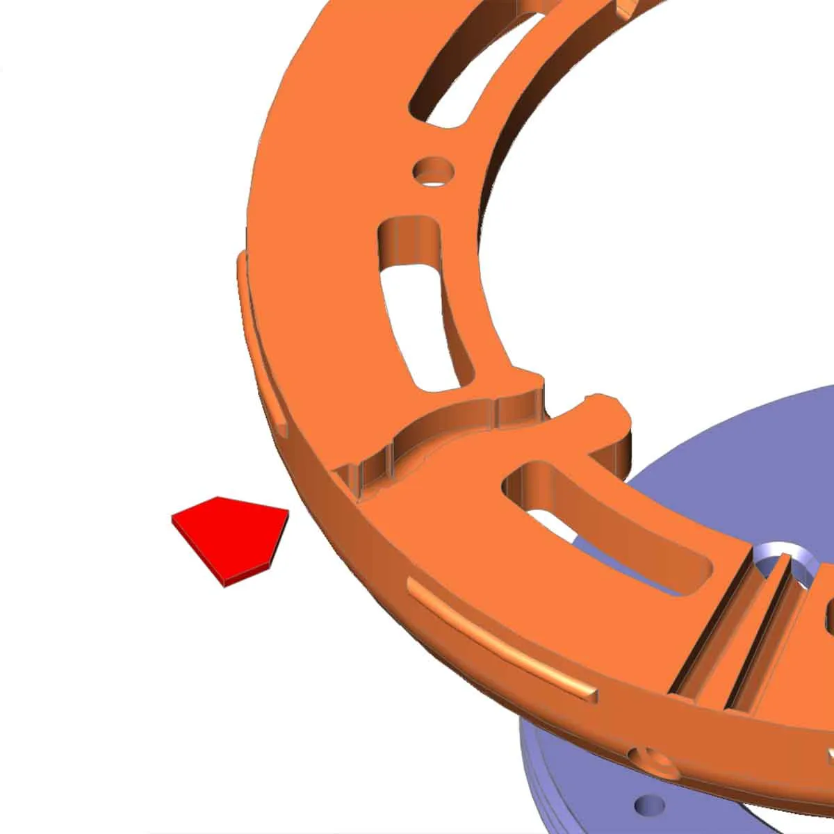
- Position, and then mount the base using #8 wood screws (or other screws which will fit in your installation). Make sure not to pinch the USB cable, and leave enough slack to connect it to the camera (but no so much that the cover will not be able to go on). When positioning the base, take note of the position of the USB-C cable passthrough, any drainage holes, and also the notch which allows the cover to go on. The notch should be offset by about 90°-180° from the corresponding gap in the cover (when in the final position, so the cover can be secured).
- Plug the USB-C cable into the camera if it is not already connected. The ball may need to be adjusted to avoid pinching the USB cable. Be sure the USB cable is not pinched or bent at an extreme angle.
- To install the cover (with the ball and camera pre-installed), first find the notch in the base, which is marked with a raised arrow around the edge. This will slot into the open area on the cover. Once it is aligned, the cover can be rotated in the track in the base and the M3x8 screw made snug to set the position. Don't overtighten the screw.
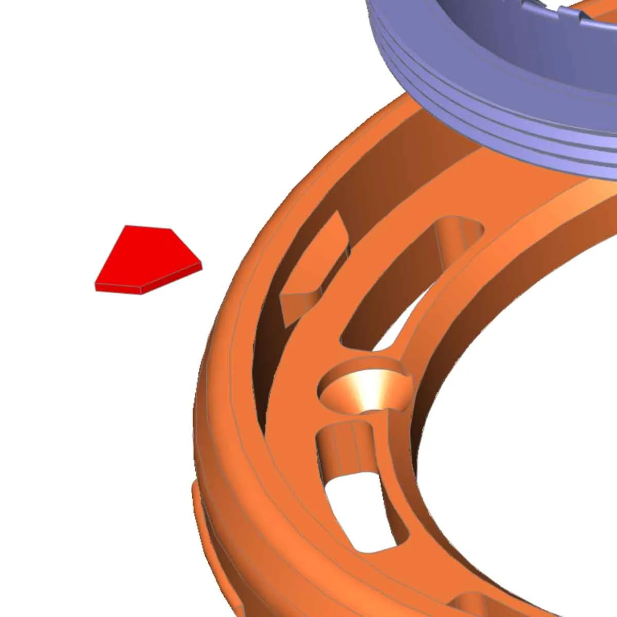
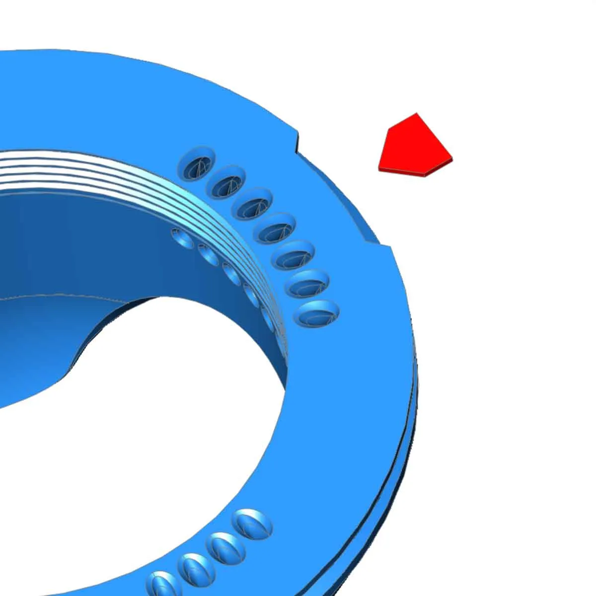
- Next, position the camera to where it needs to be aimed, and make a small mark or add a piece of tape to the cover, in line with where the M3x8 screw is located. This will help with repositioning it in the following steps.
- Carefully loosen the M3x8 screw and remove the cover. Then tighten down the ball in the final position, using the tool to tighten the threaded retainer part. The USB-c cable may need to be temporarily removed to do that. Make sure the USB-C cable is not pinched or bent at an extreme angle once it is installed with the camera aimed in the final position. Also make sure there is not too much USB-C cable slack inside the housing, so the cable does not get pinched when the cover is replaced.
- With the ball tightened down, and the camera aimed, re-install the cover on the base, and align the M3x8 screw with the mark or tape placed on the cover in step 12. Tighten down the M3x8 screw in the base so the cover is secure and does not rotate freely. Do not overtighten the screw.
- Check the function of the camera, and adjust things if needed.
Other Stuff:
The STEP models are included, which has an alternate cover with additional screw holes. If you remix this elsewhere, please post a comment, so I can check it out.
I used PETG to print this (and TPU for the gasket), other materials should work as well, but if using it outdoors, PLA is probably not the best choice.
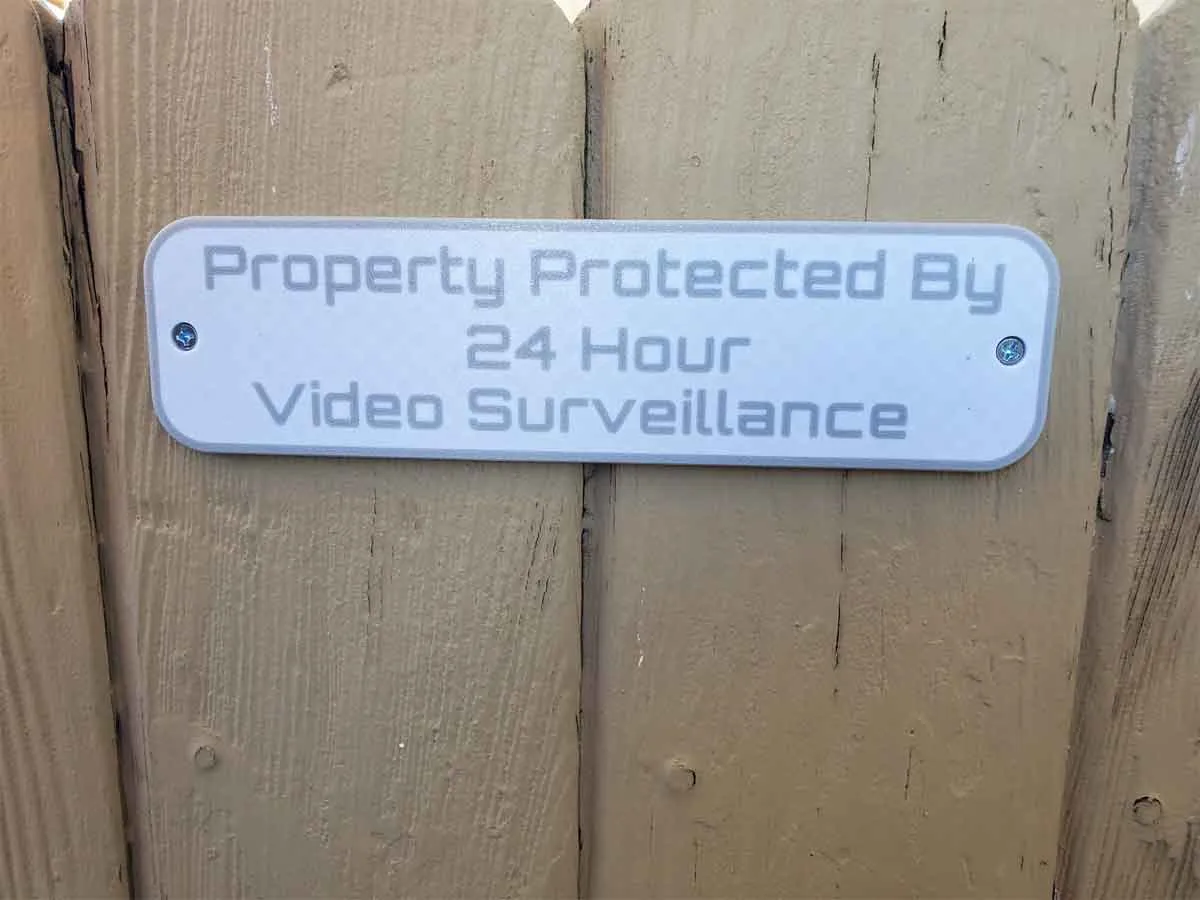
If you want a simple sign to that notifies invited and uninvited guests that video surveillance is being used on the property, you can find one here:
https://makerworld.com/en/models/761519#profileId-696242
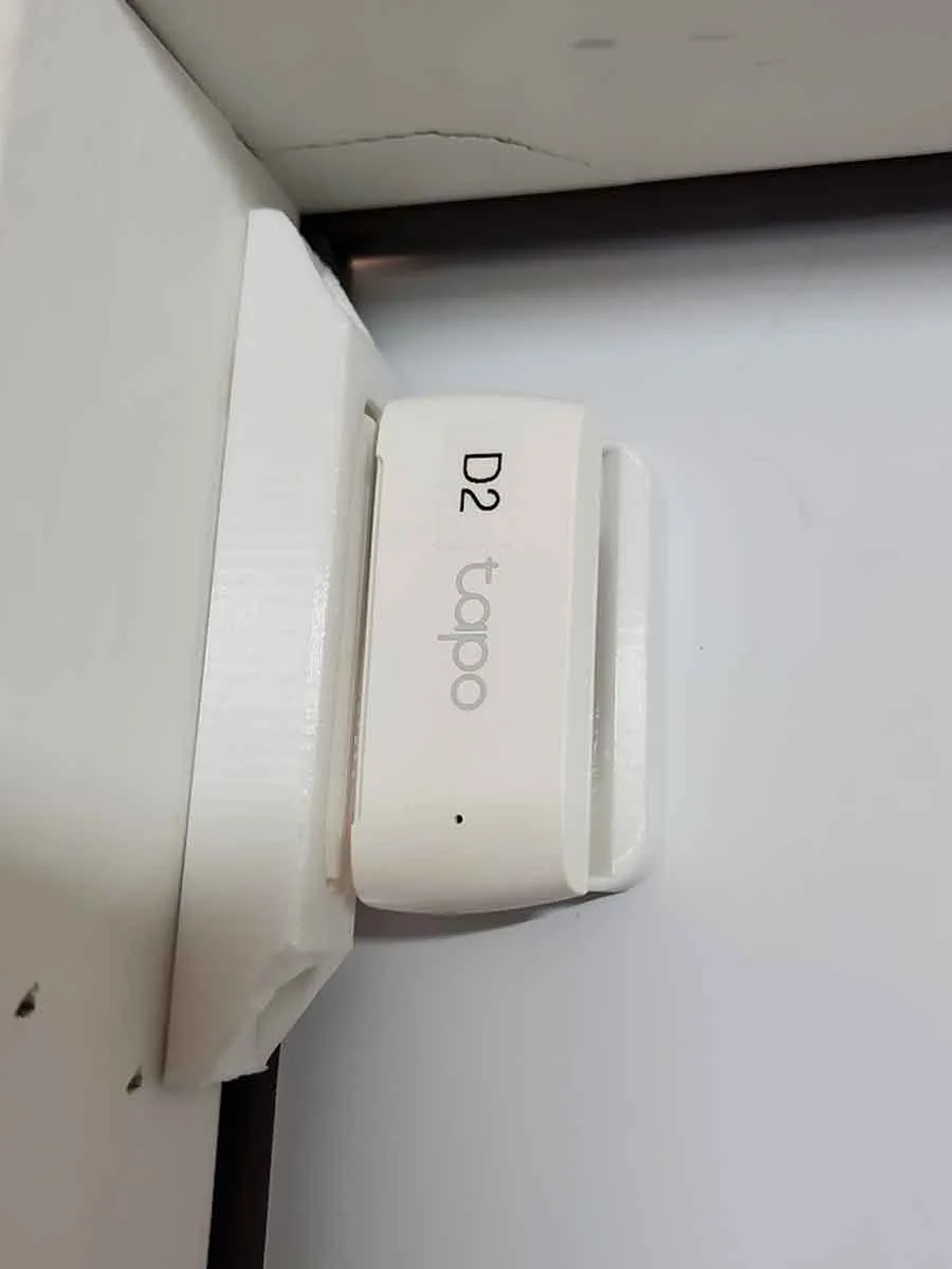
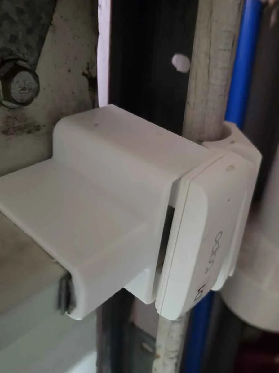
I also have a number of various mounts for TAPO T110 door sensors (including a garage door mount). You can find them at the link below:
https://makerworld.com/en/models/1613261-tapo-t110-sensor-mounts-with-step#profileId-1702013
 |  |  |
Boost Me (for free)
Thanks for supporting my work!
If you find these models useful, please post a like or a comment with some pics of your prints.
You can find the other things I'm working on at my blog here. You can also follow me here on Printables or MakerWorld, to see what new stuff I post. If you would like to support my work, you can Buy Me A Coffee using this link:
https://www.buymeacoffee.com/mystoopidstuff
Thanks for looking!
Changelog:
10/22/2024: Uploaded to Printables.
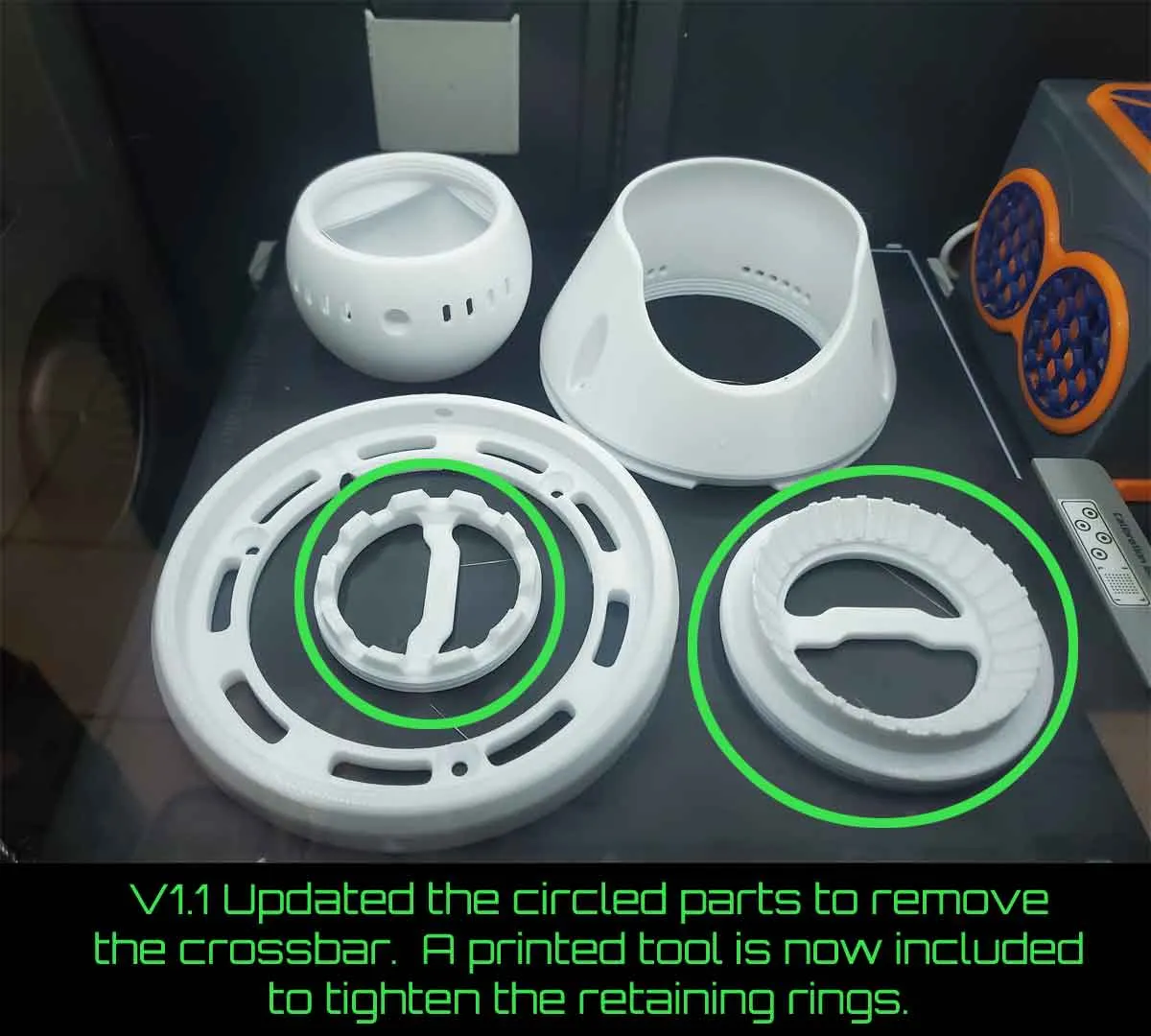
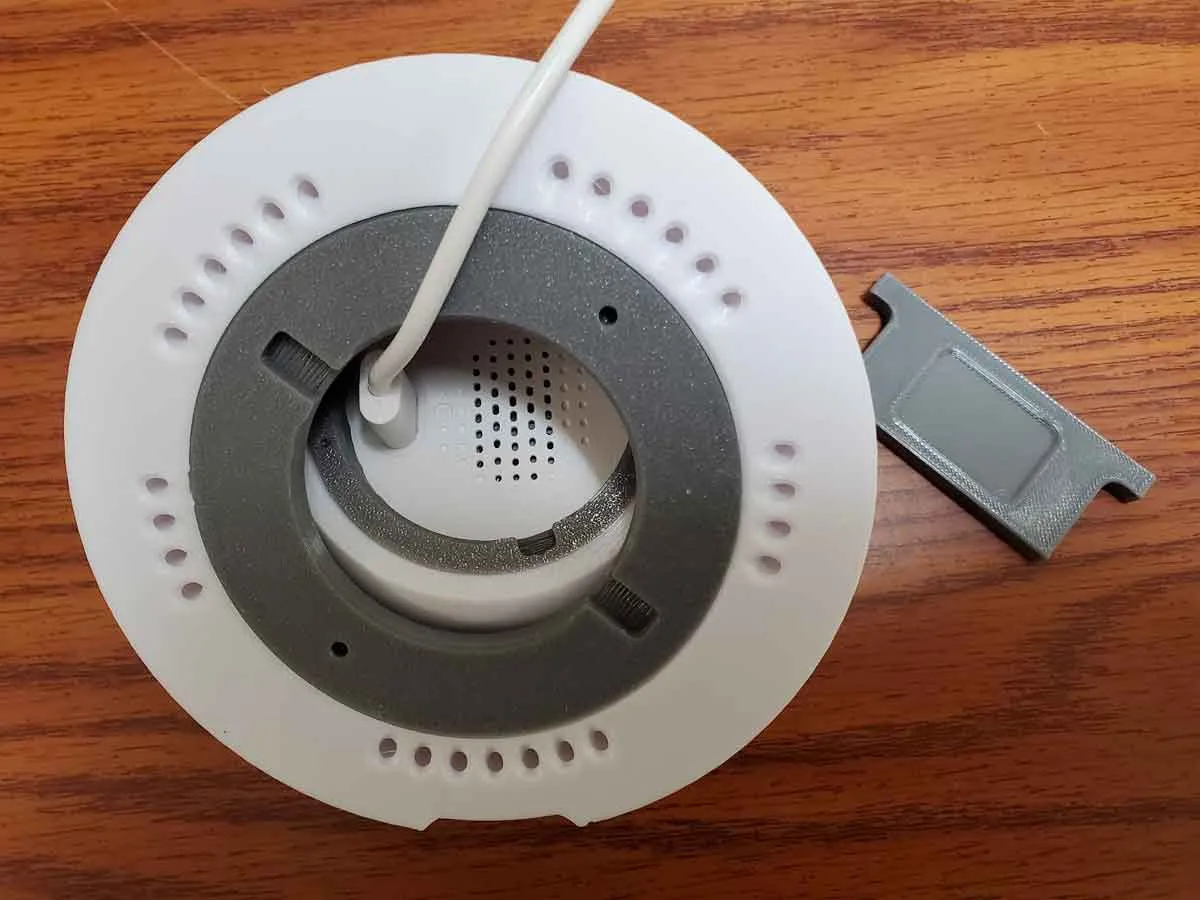
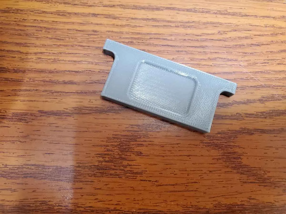
6/12/2025: Updated to v1.1. Changed the retaining ring designs to use a printed tool (included), to tighten them. The prior design utilized an integrated cross bar, which made it a bit difficult to route the USB cable to the camera.
 |  |  |
7/3/2025: Added some alternate covers (which are not tested). They are the same design as the original though, so I do not expect issues with them. The changes are to the opening for the camera, and have either a small chamfer or a larger one. The reason for the change is to hopefully reduce IR reflections from the cover, which were noted in the comments (on Printables) for a camera which was aimed at the near max extent of the range (closer to horizontal). There are two types of each new alternate cover, and each has a version with, or without screw holes for securing the cover further (so a total of 4 options). The pics below show the two types.
I do not plan to test these at this time, but if you do, please drop a comment and let me know how they work, and if they reduce IR reflections when the camera is pointed mostly horizontal. The files are only available as the STL (and STEP) for now (no 3mf until they are tested), and are located in the folder named “Alternate Untested Covers”.
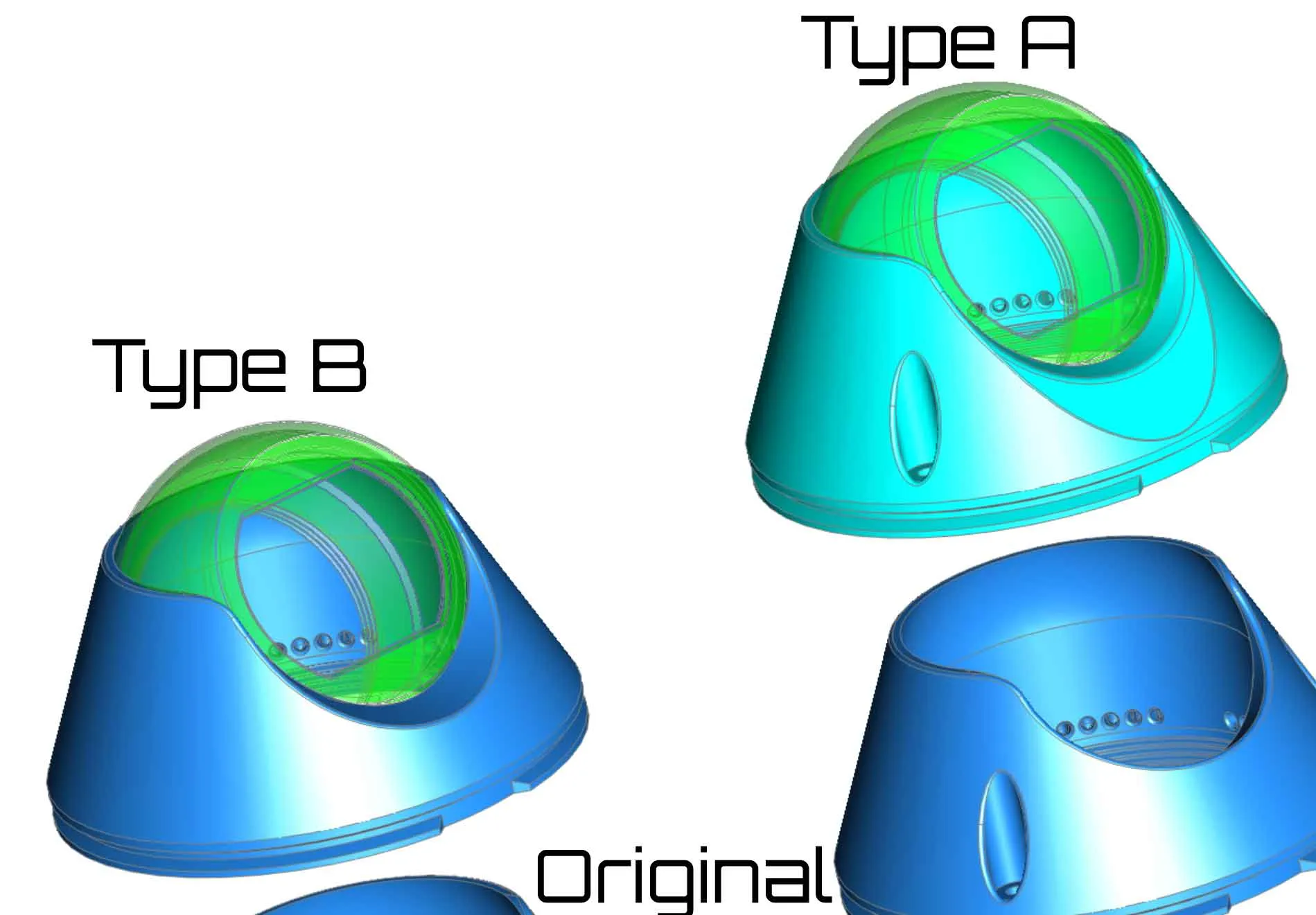 |  |
2/15/2026: Thanks to the users in the comments who have tested these covers. So far the TypeA cover is confirmed to work well, so I recommend using it, if the camera needs to be positioned in the mount at a low angle. I updated the 3mf profile to v34, with these optional covers.
4/14/2026: I added an alternate base which is designed to hold 18x 10x3 cylinder magnets. This base is not tested, so if you use it, please provide feedback. The alternate magnet base can be found only in the files (in the folder “Alternate Untested Magnetic Base” > TAPO-CAMmountv35MagneticBase.stp). This part is not included in any of the 3mf profiles, since it has not been tested.
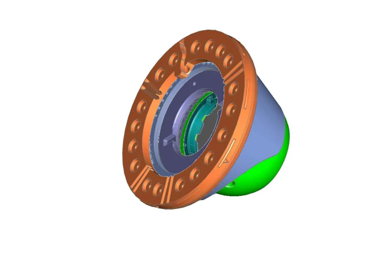 | 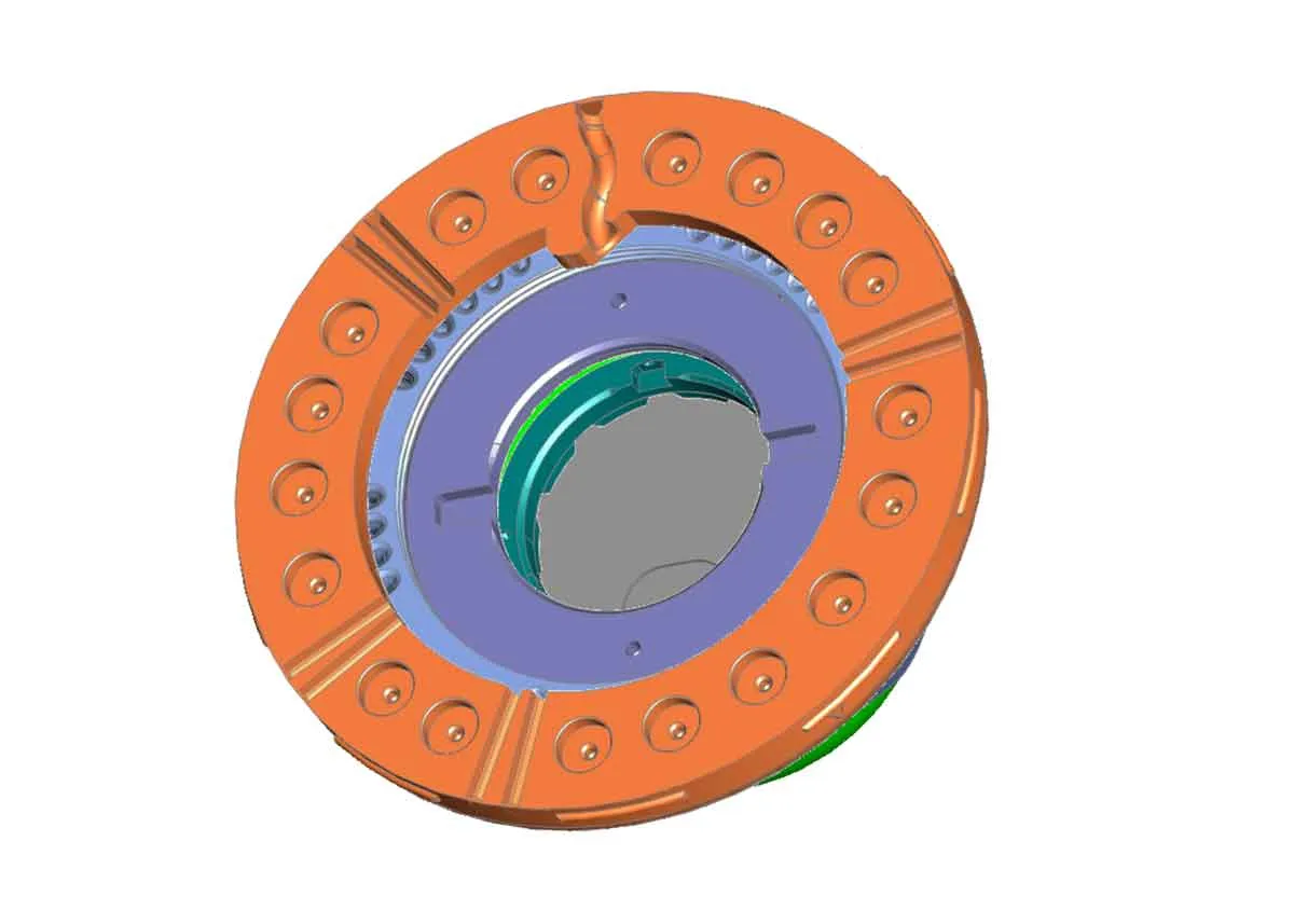 |
License



Comment & Rating (8)