CUSTOM Lithophane magnetic frame


Print Profile(1)

Bill of Materials


- USB-C female connector with pcb x 1: https://vi.aliexpress.com/item/1005005996991234.html
- PogoPin - 2Pin, 2.54mm, with ear x 10: https://vi.aliexpress.com/item/1005005605267060.html
- Wires (silicone and hard 16AWG) x 1: used for wireing
- crew M2x4mm x 2: small screws for screwing usb-c pcb
Description
Hello everyone.
I’m happy to show you my way of lithophane frames :)
They are combinations of frame sides with different options and together they create a beautiful, slim frame for lithophanes. Frames are designed to hold lithophanes that are the same size that go into the original BambuLab lithophane stand (108×144×2.7mm). The frames size of each frame is 117×156×20mm with nice and thin bezels. The frames are designed in a way that they can be easily put together and are held together with other frames via magnets and to supply power they use PogoPins.
For lighting up the lithophanes i used LED stips and i must say, it looks nice :)
Explanation of parts
In the next tables i will explain what the names for parts mean :)
Blank frame parts:
Name of the part | Explanation |
|---|---|
OG L | Frame part that is used in LEFT position when looking from the front of the frame |
OG T | Frame part that is used in TOP position when looking from the front of the frame |
OG R | Frame part that is used in RIGHT position when looking from the front of the frame |
OG B | Frame part that is used in BOT position when looking from the front of the frame |

So the first part of the naming schemes are always description of their functionality. Next table shows all the possible naming schemes for frame parts that have USB-C slot. Each piece can be used in 2 orientation so i described where will the be position for each piece (diferent position of the pisece is devided by - in the naming):
USB-C Frame parts:
Naming after USB-C part | Position of USB-C port when looking from the front of the frame |
|---|---|
BL - TR | Bot frame Left side - Top frame Right side |
BM - TM | Bot frame Middle side - Top frame Middle side |
BR - TL | Bot frame Right side - Top frame Left side |
LB - RT | Left frame Bot side - Right frame Top side |
LT - RB | Left frame Top side - Right frame Bot side |
There are 2 veriants of USB-C frame parts. With or without magnets. They are named and i also named the plate for easier understanding wich is wich. Same goes for blank frame parts.


PogoPin Frame parts:
Naming after PP part | Position of PogoPin port when looking from the front of the frame |
|---|---|
BL - TR | Bot frame Left side - Top frame Right side |
BM - TM | Bot frame Middle side - Top frame Middle side |
BR - TL | Bot frame Right side - Top frame Left side |
BLP - TLR | Bot frame Left & Right side - Top frame Left & Right side |
LB - RT | Left frame Bot side - Right frame Top side |
LT - RB | Left frame Top side - Right frame Bot side |
Mounts for frames:
Naming | Explanation |
|---|---|
Wide | Wide mount for longer side of the frame assembly. e.g Used for screwin to the shelf from the top |
Wide Wall | Wide mount for longer side of the frame assembly. eg Used for screwing to the wall directly. |
Narrow | Narrow mount for shorter side of the frame assembly. e.g Used for screwin to the shelf from the top |
Narrow Wall | Narrow mount for shorter side of the frame assembly. eg Used for screwing to the wall directly. |
Assembly:
This is desighned in a way that you need to be skilled with hands a bit. Was desighned so i can put it together and i didnt had it in mind that it would be eazy to put toggheter for other people :/ so pls have some patiance :p
some electronical knowlage required
soldering required
I will not be responsible for incorrect polarisation of the wires during soldering process
- Setting up LED plate
Print the LED plate in whatever color you want. I realised that when i printed mine in black pla i didnt get any back underglow but when i did it with colored pla like Cyan color from bambu lab, i got slight under glow behind lithophane when it was lit. So there is little something if you want to experiment with :)
So to asemble LED plate you will need to cut 6 LED strip per plate (8 LEDs per strip). Glue them with the provided double sided tape to the LED plate. I desighnes some aligment into the model so they are nice and straight and evenly distributed on the plate

Next i ussed solid wires and cut them into 20mm long pieces and stripped the and and bent them 90° and soldered them. Solder them to one side and connect all + and - seperatly.

- Chose 4 sides of the frame and prepare them
- If you chose any of the sides to be OG, they dont need preparation.
- If you chose any of the sides that have magnet holes, i reccomend that you insert magnet into them right now. I would advise that direction of the magnets is the same with all of the frames. Magnets should have snug fit, if they dont use supper glue.

- If the frame part include USB-C port then screw it to the part using M3x4mm screw. I reccomend to orient the board like i did in the picture since i will be easier to solder the wires to it later on.

If frame parts have PogoPins its better to insert them into parts now.
WHEN ADDING POGOPINS BE AWARE OF THE ORIENTATIONS SINCE THEY SNAP TO ONLY ONE ORIENTATION.
Pressfit them into the slots (add superglue if they are loose but i tested with 2 printers and they were always snug fit).
I reccomend to use pogopin with pins on the frame part that recives power from previous frame.
Solder wires to pogopin (aprox 20-30mm).
- Adding the 3 corners of the frame to the plate
Now is going to be the time to screw together 3 corners of the frame together. Chose LEFT or RIGHT side of the frame and top and bot side. Using m3x8mm screw, screw one of the shorter frame parts to both longer frame parts. KEEP IN MIND THE ORIENTATION OF THE INNER SLOTS. THEY SHOULD NICELY OVERLAP. If they dont overlap nicely just rotate the longer frame part 180°.


Next slide LED plate into the slot of LED plate.

- If you have frame part with pogopins or USB-C now is the time to solder them to the LED panel. Connect the + and - to the correct

- Add the diffuser and lithophane layer.
Now is the time to add diffuser layer and lithophane layer to the frame. Just slide them in their slots untill the end.
- Close the frame
You are now almost done. Just close the frame with the last narrow part of the frame remaining and screw the 2 M3x8mm screws.

Just repeat all these steps for other frames you wish to build.
Happy making :)
Example of my frames:
So for the first frame i have a cute little bird that recives power trough USB-C on the left frame and it has magnetic frame on top for mounting to mount. Right side has PogoPin frame as well as Bot side. But i ussed Frame on the botom with 2 pogopins (PP BLR-TLR).
| Materials for bird frame | Count |
|---|---|
| LED panel | 1 |
| Diffuser | 1 |
| USB-C LT-RB | 1 |
| OG T magnets | 1 |
| PP LT-RB | 1 |
| PP BLR-TLR | 1 |
The next one lets say its the JO-JO one. Top frame is PP BL-TR, left frame is magnet one, bot frame is PP BL-TR and right frame is magnets again. I used magnetic frames on the sides because it will give better magneti connection to frames on left and right side. You could eazily use normal frame without magnets here no problem :)
| Materials for JO-JO frame | Count |
|---|---|
| LED panel | 1 |
| Diffuser | 1 |
| OG L | 1 |
| OG R | 1 |
| PP BL-TR | 2 |
I hope that you understand how this works now XD
I tried to make it as logical as possible, well at least for me :p
Materials used in the project:
- printed frame parts
- USB-C female connector with pcb
- PogoPin - 2Pin, 2.54mm, with ear
- LED strip - white light 60leds/m
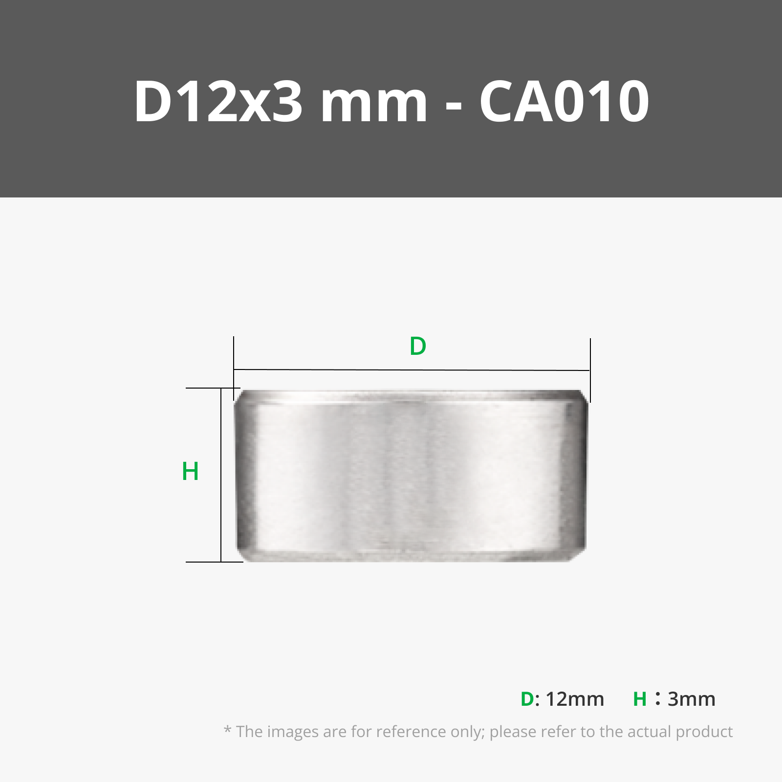
- Magnets - Round, 12×3mm
- Hard wires - 16AWG
- Soft silicon wires - 16AWG
- Screw M3x8mm
- Screw M2x4mm
Boost Me (for free)
It would help a ton if you drop a review, like or maybe a boost if i deserved it ;)
Feel free to print some of my lithophanes as well :)
Have a great day and happy printing :D
License
You shall not share, sub-license, sell, rent, host, transfer, or distribute in any way the digital or 3D printed versions of this object, nor any other derivative work of this object in its digital or physical format (including - but not limited to - remixes of this object, and hosting on other digital platforms). The objects may not be used without permission in any way whatsoever in which you charge money, or collect fees.
Comment & Rating (4)