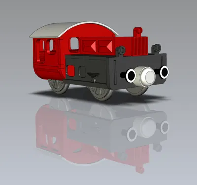
Köf II - Wooden Train - Wooden Railway - v2


Print Profile(2)


Bill of Materials


Description
Köf II version 2 compatible to IKEA, Lidl or Brio wooden train systems.
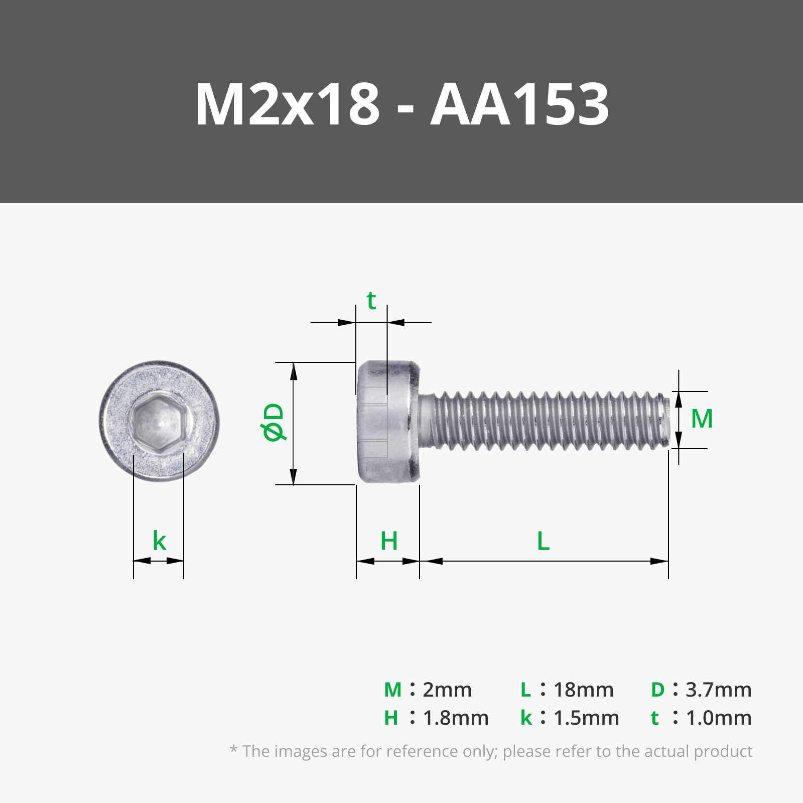
The whole model can be plugged together and will be fixed with 4 screws: 2x M2x5mm 2x M2x18mm
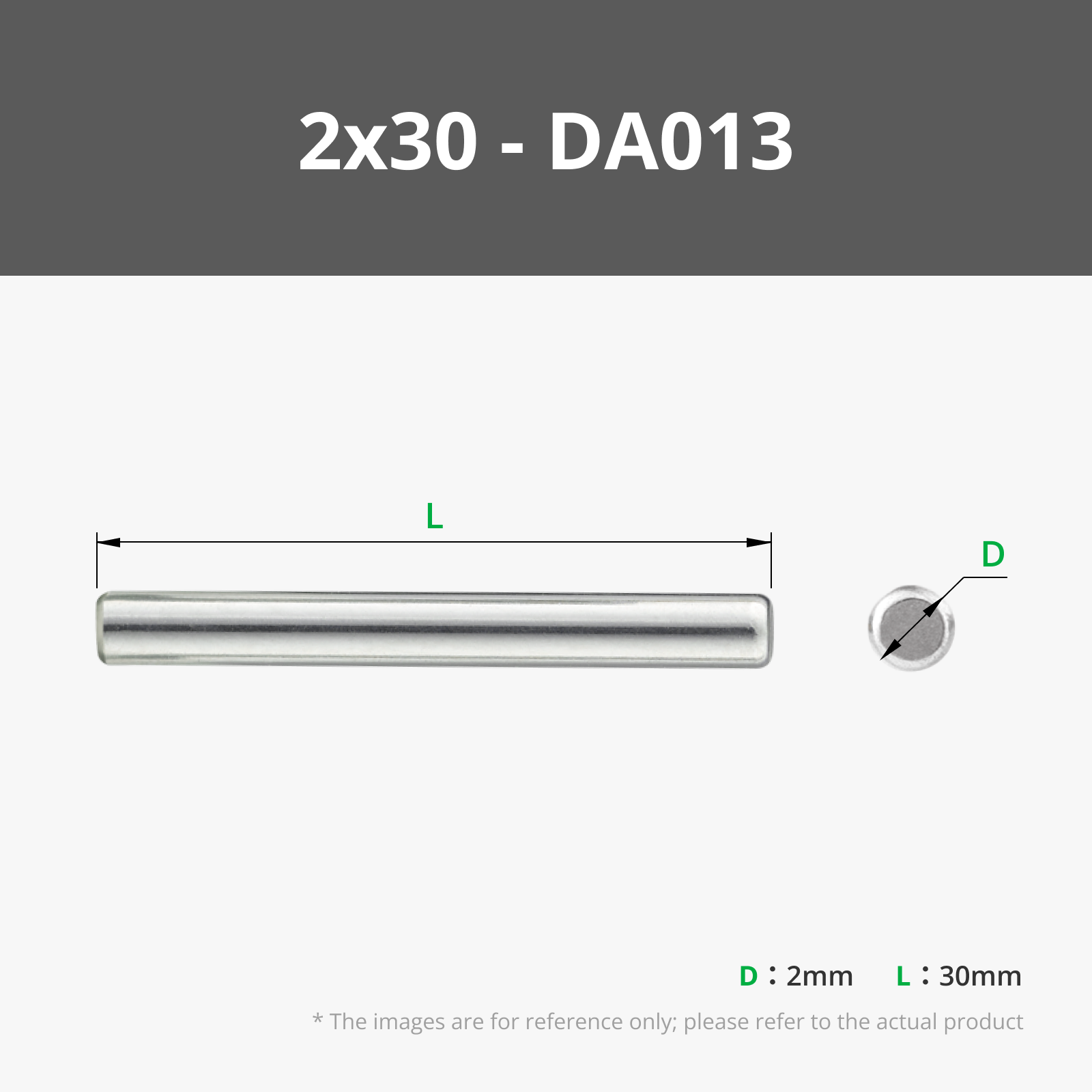
The wheels can be put in a metal 2mm shaft with a length of 30mm. The wheels wholes may need some drilling, so the shaft is not locking the wheels.
A complete guide how to assemble will follow soon!
Parts:
Operators cap:
- Back: 1x schreinerman-holzeisenbahn-köf2-v2-Führerhaus-Hinten.stl
- Front: 1x schreinerman-holzeisenbahn-köf2-v2-Führerhaus-Vorne.stl
- Side: 2x schreinerman-holzeisenbahn-köf2-v2-Führerhaus-Seite.stl
- Bottom: 1x schreinerman-holzeisenbahn-köf2-v2-Führerhaus-Boden.stl
- Top: 1x schreinerman-holzeisenbahn-köf2-v2-Dach.stl
Chassis:
- Main: 1x schreinerman-holzeisenbahn-köf2-v2-Fahrgestell.stl
- Left: 1x schreinerman-holzeisenbahn-köf2-v2-Trittbrett-links.stl
- Right: 1x schreinerman-holzeisenbahn-köf2-v2-Trittbrett-rechts.stl
- Fromt: 1x schreinerman-holzeisenbahn-köf2-v2-Front.stl
Engine bonnet:
- 1x schreinerman-holzeisenbahn-köf2-v2-Motorhaube.stl
Wheels:
- 4x schreinerman-holzeisenbahn-köf2-v2-Rad.stl
Bumpers:
- 4x schreinerman-holzeisenbahn-köf2-v2-Puffer.stl
Building instructions: https://holzeisenbahn-schreinerman-de.translate.goog/koef-ii?_x_tr_sl=auto&_x_tr_tl=de&_x_tr_hl=de&_x_tr_pto=wapp
component list (not printed)
4x Zylinderkopfschraube M2 x 5mm
2x Zylinderkopfschraube M2 x 18mm
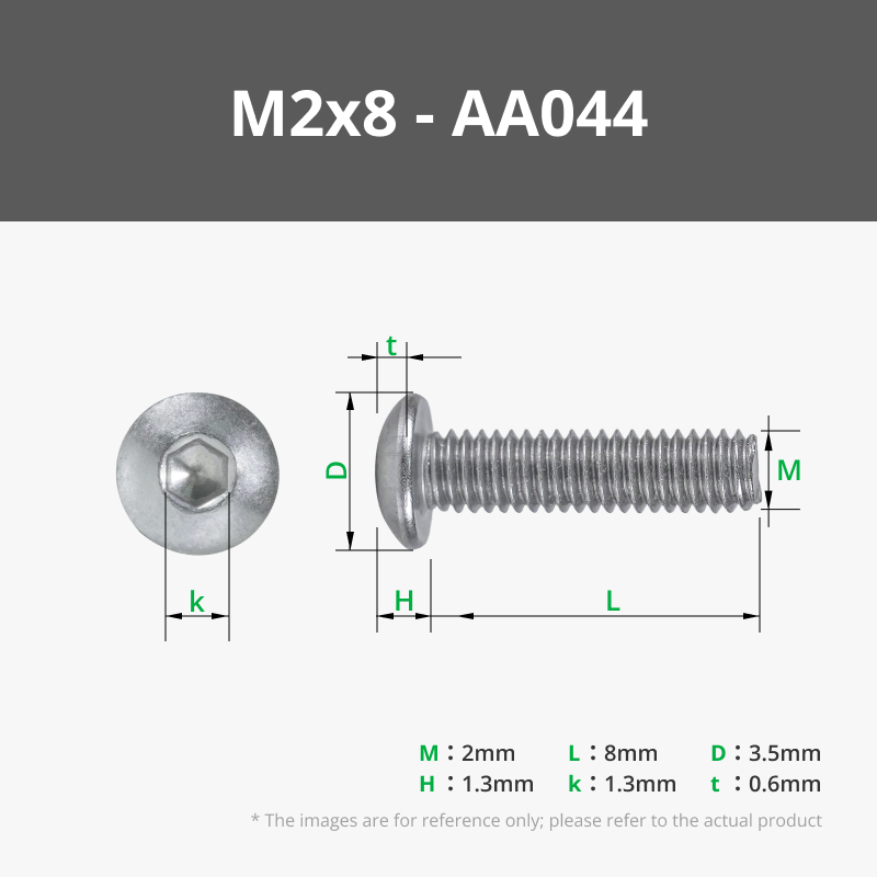
2x Linsenkopfschraube M2 x 8mm
2x Stahl-Stift / Welle Ø 2mm x 30mm
2x Magnet Ø 6mm x 3mm
component list (3D printed)

1x rear cab

1x front cab

2x cab side

2x cab floor

1x Roof

1x chassis

1x running board left

1x running board right

1x Front

1x hood

4x Rad

4x Puffer

2x Magnetkappe
assembly instructions

Step 1

Screw the front to the chassis with 2x countersunk screws M2 x 5mm
Step 2

Screw the hood to the chassis with 2x countersunk screws M2 x 18mm
Step 3

Insert a shaft Ø 2mm x 30mm through the chassis. One option for the shaft is 2 mm welding wire cut to 30 mm. 30 mm rods with Ø 2 mm are also available from Amazon: https://www.amazon.de/dp/B00LUT2M6U
Step 4

Attach the wheels (if necessary, drill them by hand with a 2mm drill)
Step 5

Insert the running board left and right into the front
Step 6

Put the front cab part on the chassis
Step 7

Insert shaft Ø 2mm x 30mm through the chassis
Step 8

Attach the wheels (if necessary, drill them by hand with a 2mm drill)
Step 9

Slide the floor of the cab onto the chassis
Step 10

Insert cab side panels
Step 11

Screw the rear part of the cab to the chassis with 2x countersunk head screws M2 x 5mm
step 12

attach the roof
Step 13

Press a magnet Ø 6mm x 3mm into each of the two magnet caps with opposite polarity
Step 14

Fix 2x magnetic caps with lens head screw M2 x 8mm
step 15

Glue 4x buffers
Disclaimer:
✖ NO Sharing without ATTRIBUTION
✖ NO Remix Culture allowed
✖ NO Commercial Use
✖ NO Free Cultural Works
✖ Does NOT meet Open Definition
I decided to choose a closed license, but make models free available for everyone. Why did I made this decision? For my models I'm investigating a massive time effort in my private time. It is my decision to spent my time for this purpose and it is also my decision to have full control, how I share models with the community. As soon I'm would open my designs to remix it, share it, etc. others would make use of my effort to high-light themselves without having the control from my side anymore. This happens for example at YouTube for some influencers who are stealing the show. For me it is not about to be influencer or to make a show out of it. I'm also not ok others are doing that for me without any tribute for my effort! Please keep me informed if anybody is selling my models, which is not allowed from my side!
Comment & Rating (19)