

Print Profile(1)

Bill of Materials
- ArduinoNano33_ESP32 x 1:
Description
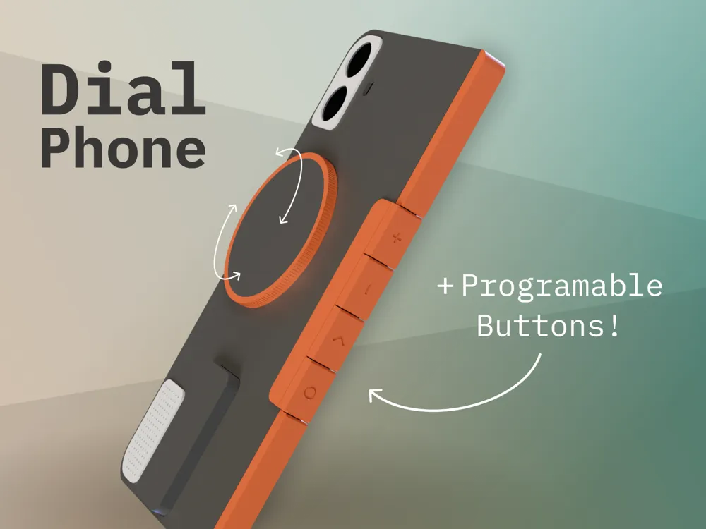
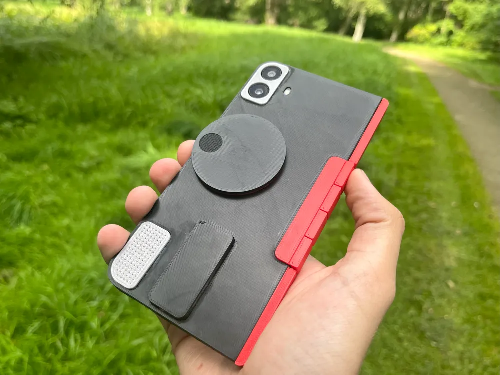
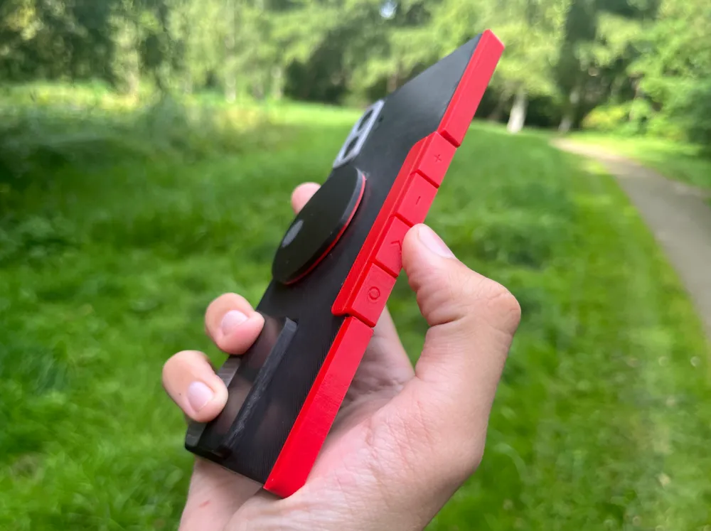
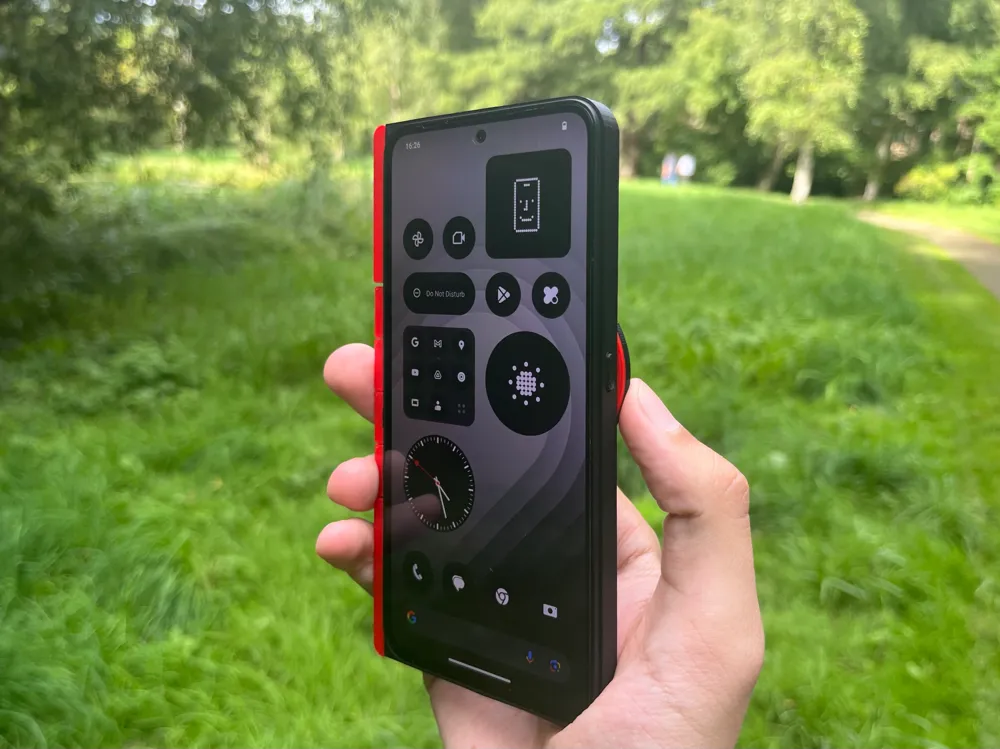
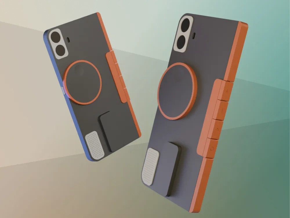
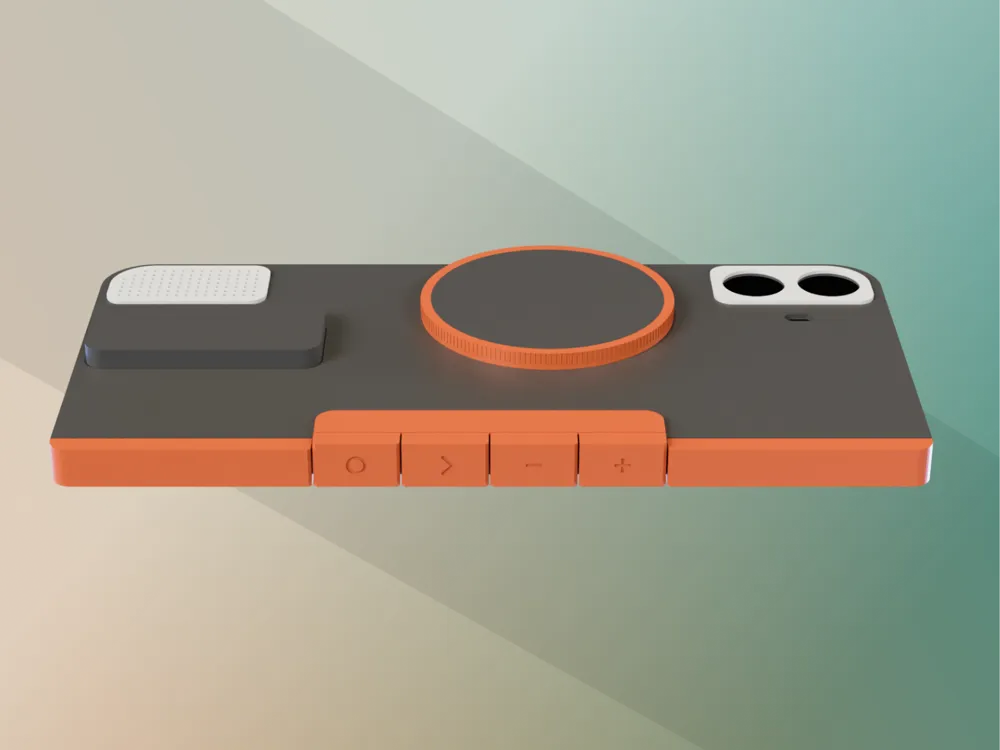
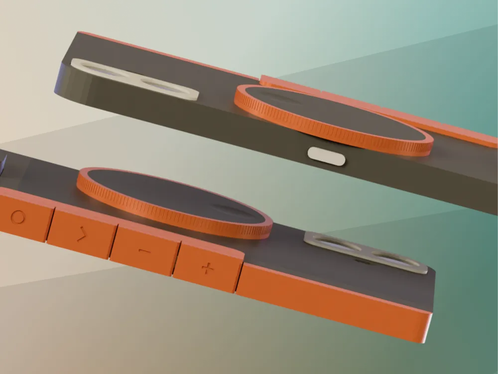
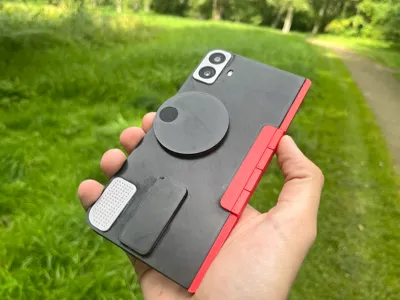
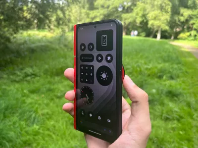
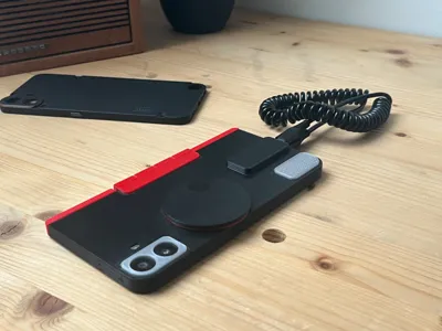
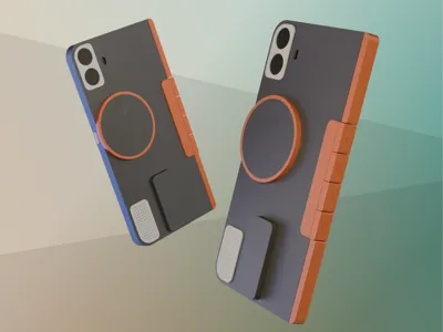
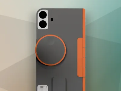
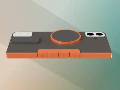
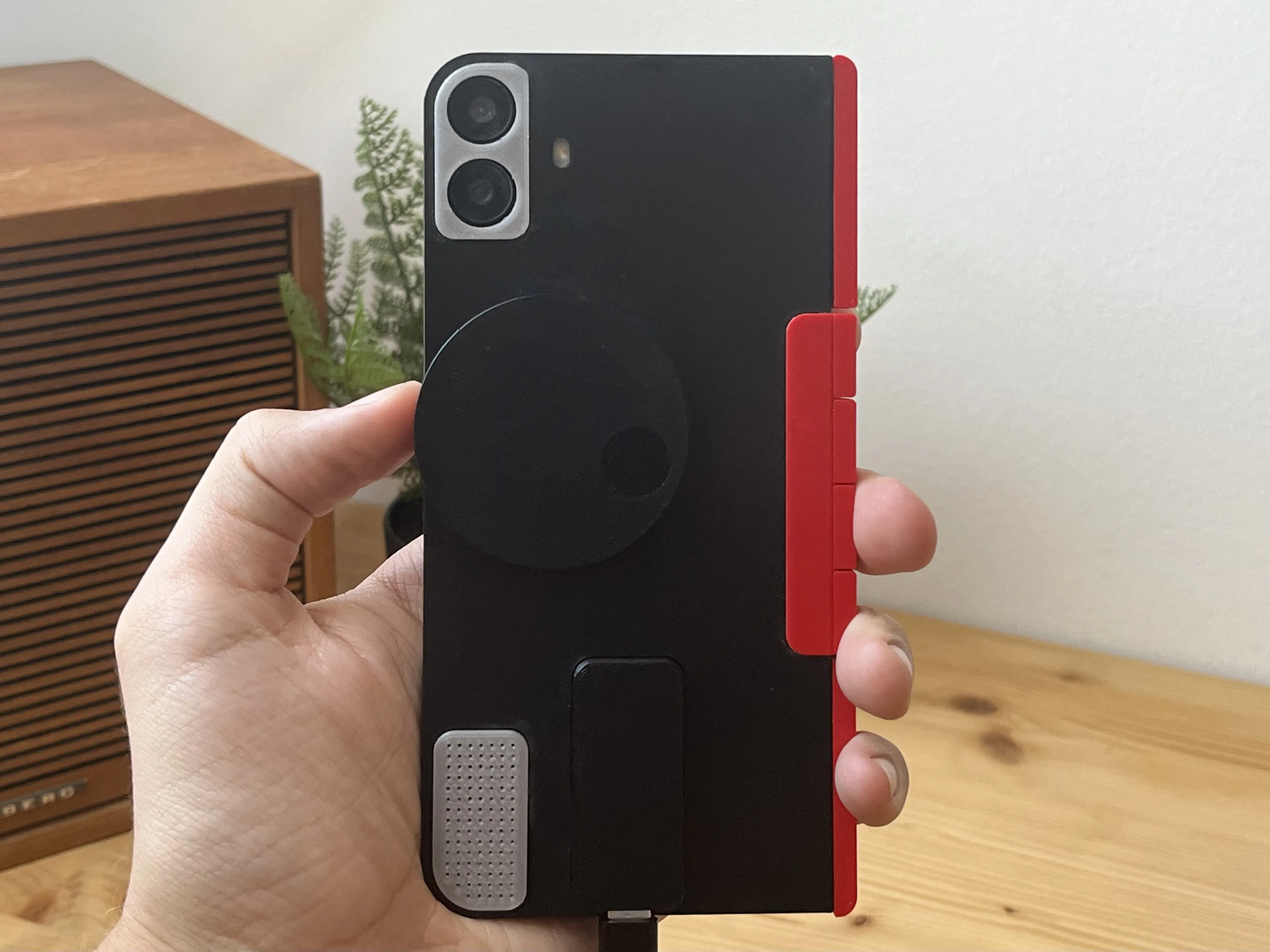
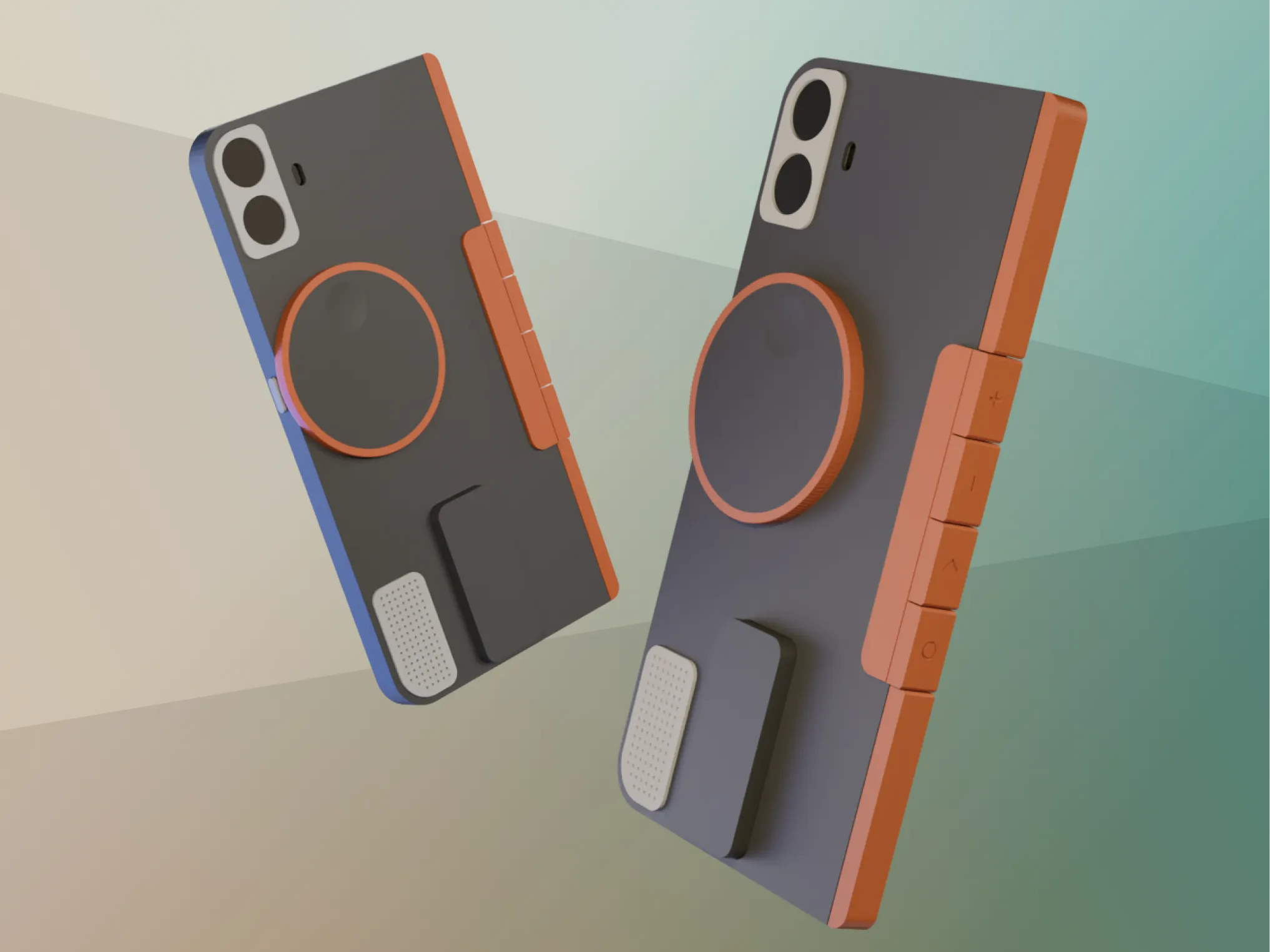
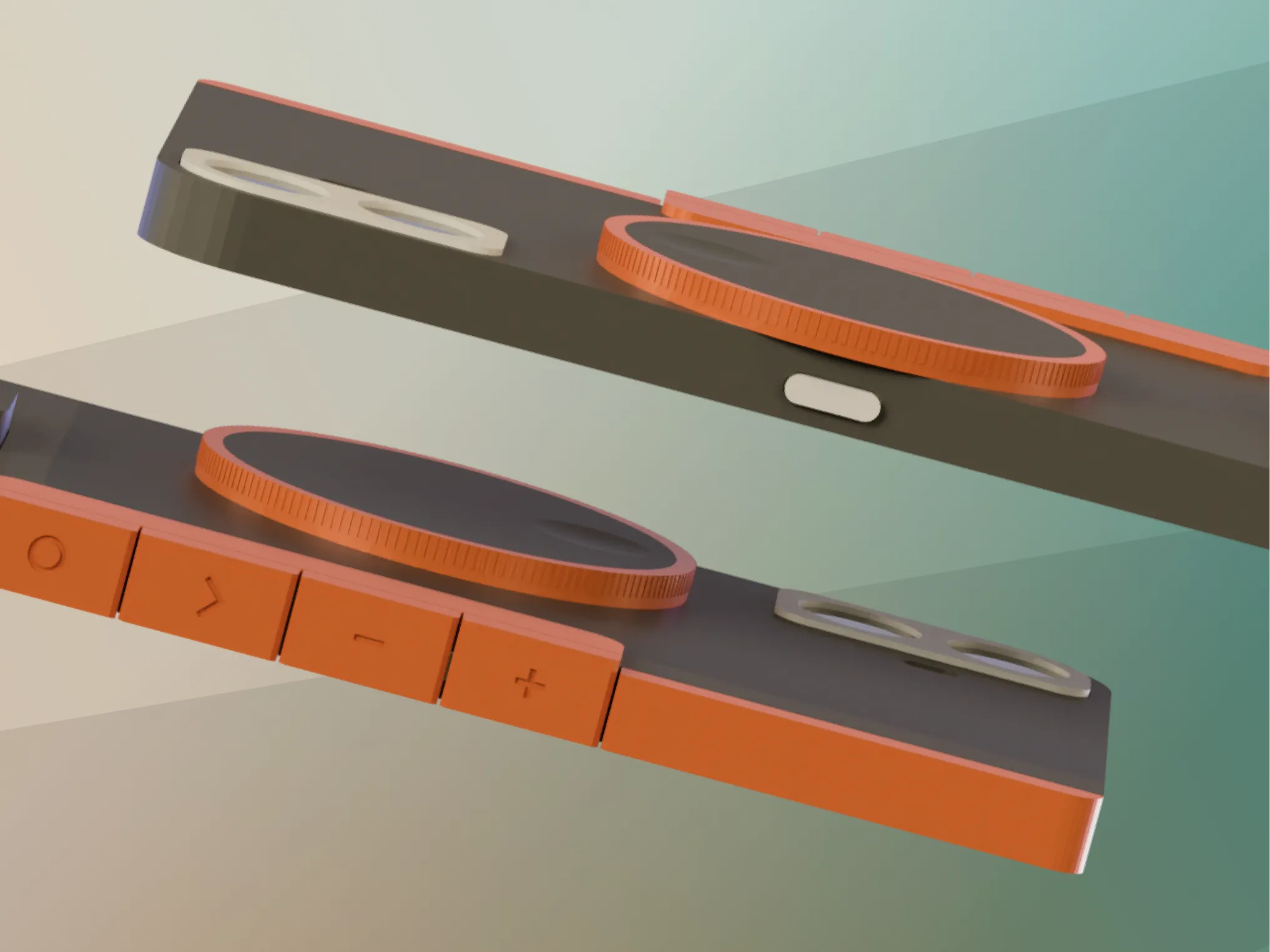
Bring a Dial & Programable Buttons to your CMF Phone!
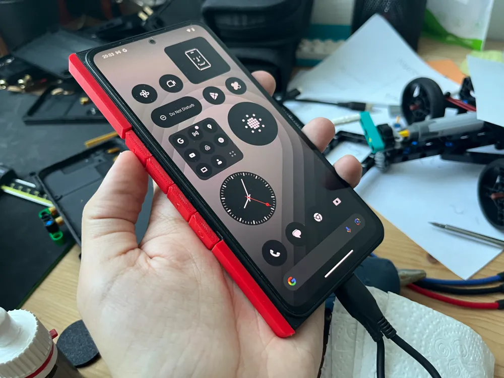
This experiment explores additional hardware interfaces on the CMF Phone 1.
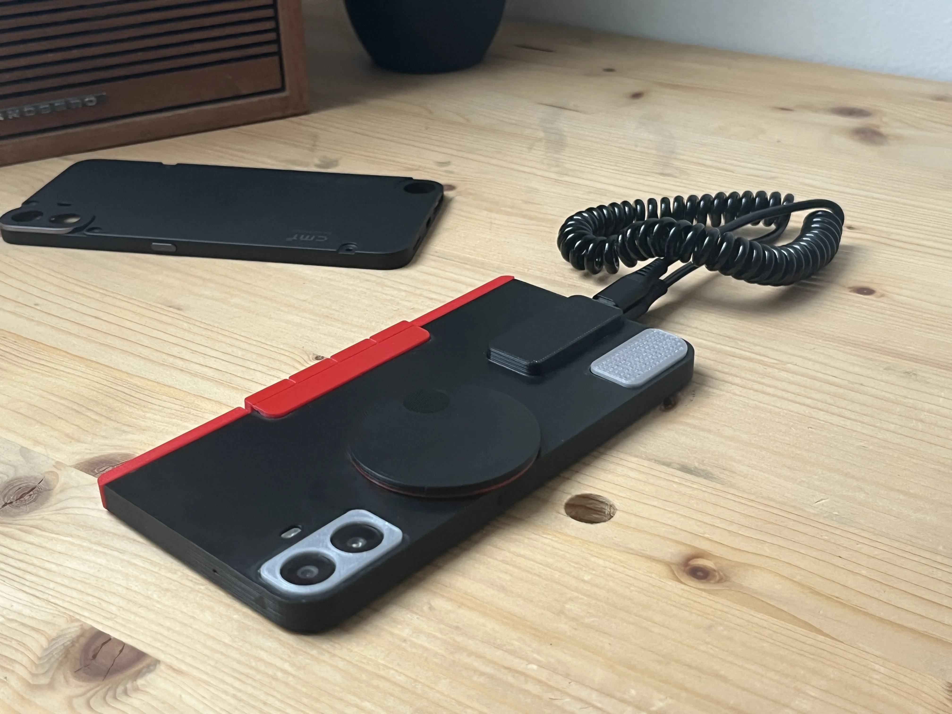
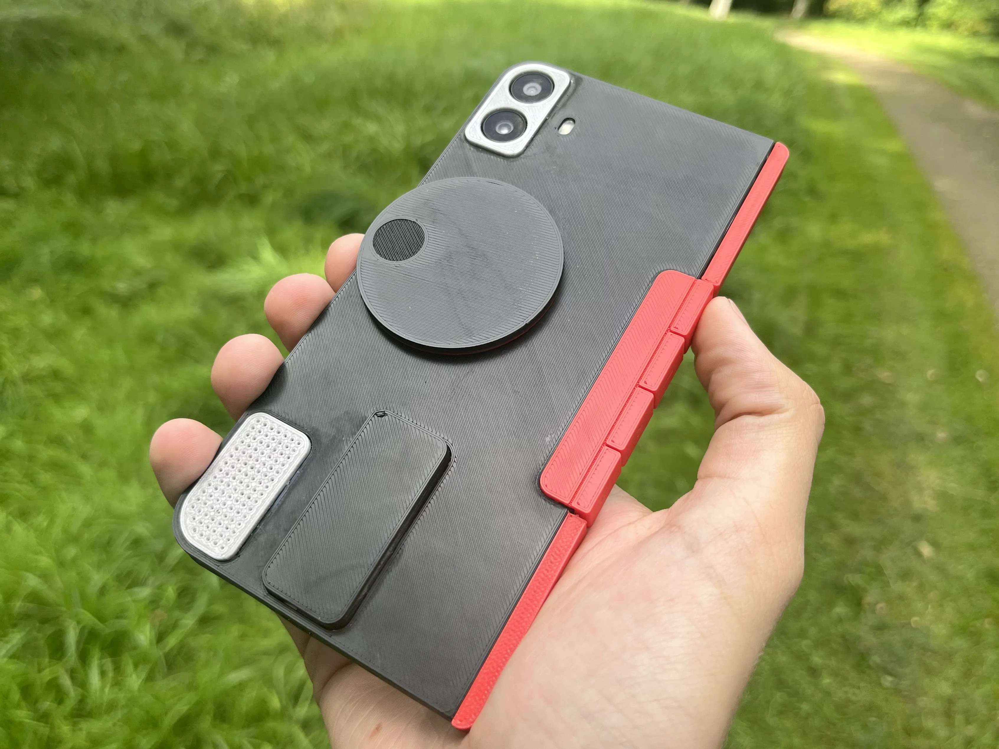
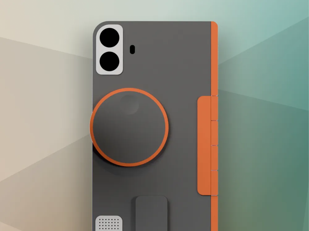
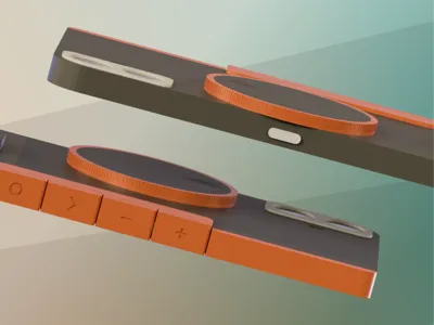
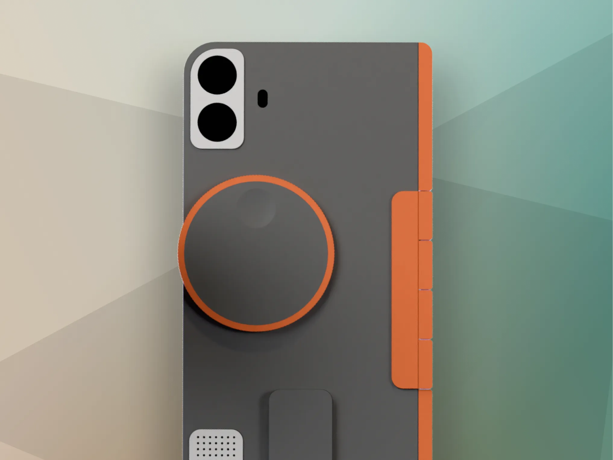
The model can be made with the Dial and Programable Buttons, or just the Programmable Buttons (note that dial is not functional yet).
Extra Buttons!

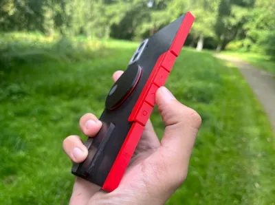
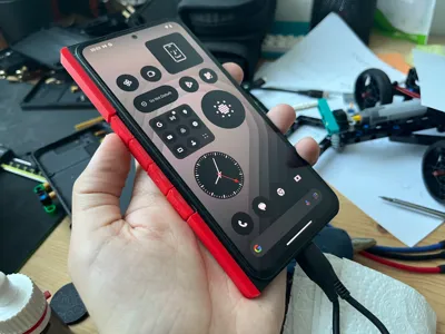
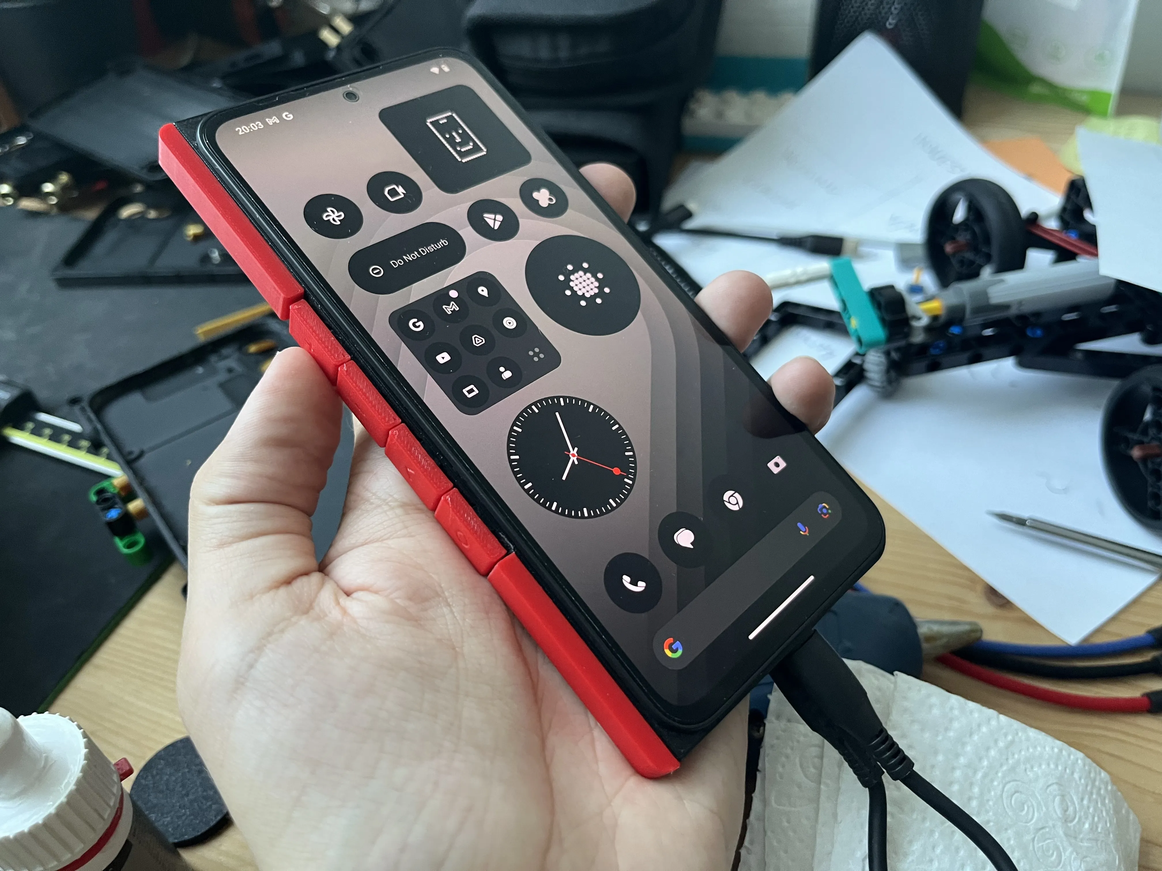
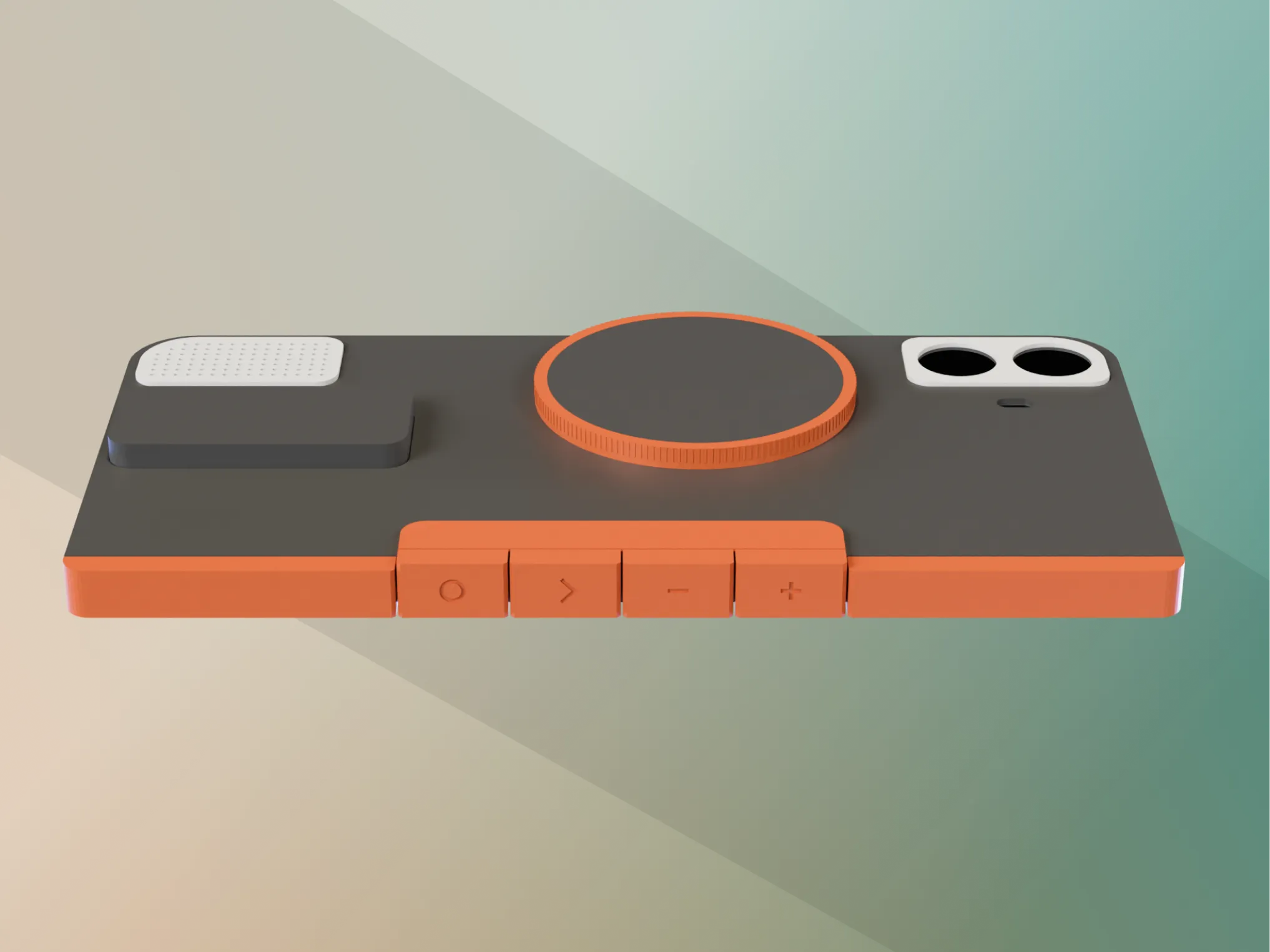
Two additional buttons can be programmed as quick-actions or shortcuts.
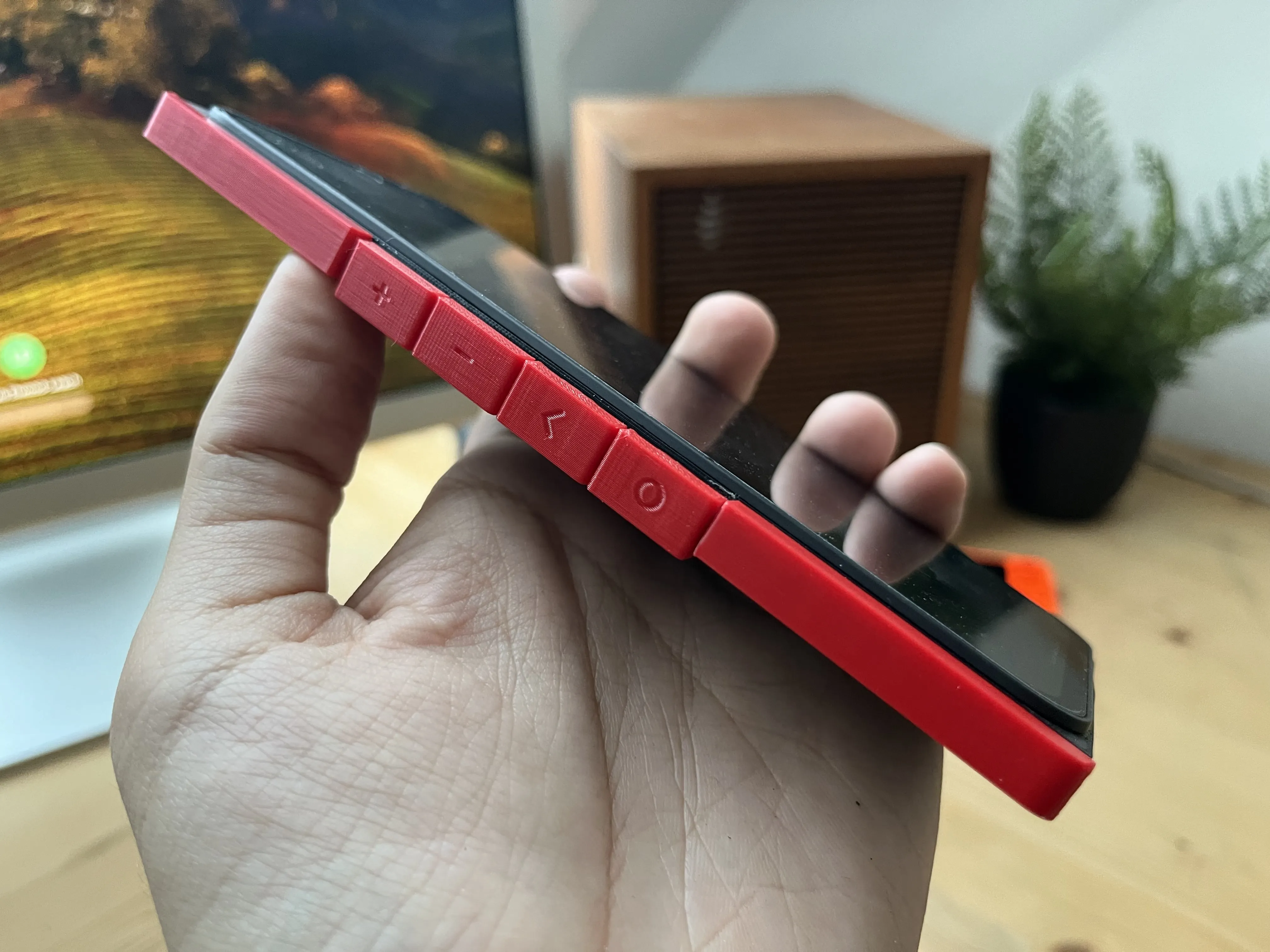



Currently, I have one mapped as a back button, and the other to quickly switch apps. I am still exploring how to use this for more specific actions. I would love to have one button start a voice chat with Chat-GPT, and the have the second button to send a voice message directly to my mum...
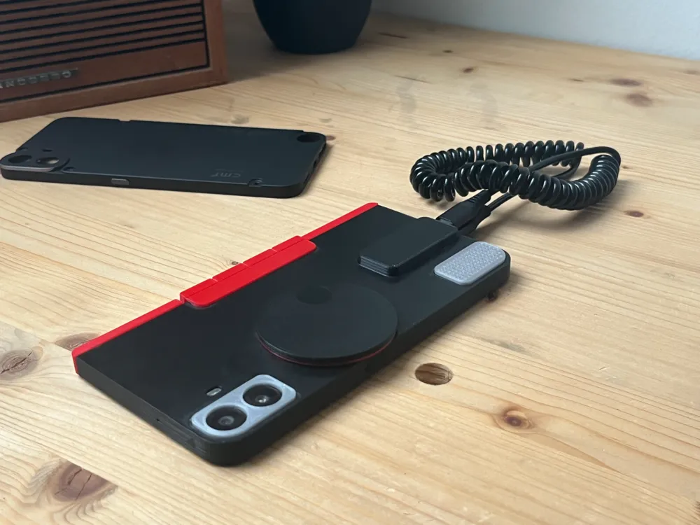
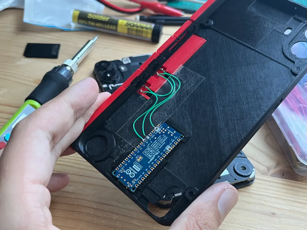
These work by having tact-switches connected to an Arduino that acts as a keyboard input. This also means that the Arduino needs to be plugged into the phone to function. Maybe there is a way of getting power from inside the phone and connecting via Bluetooth..?
What would you use two additional buttons for?
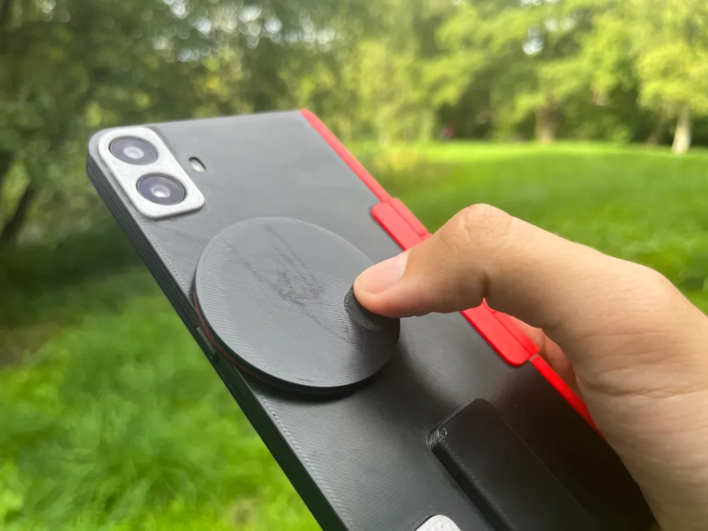
A Dial!
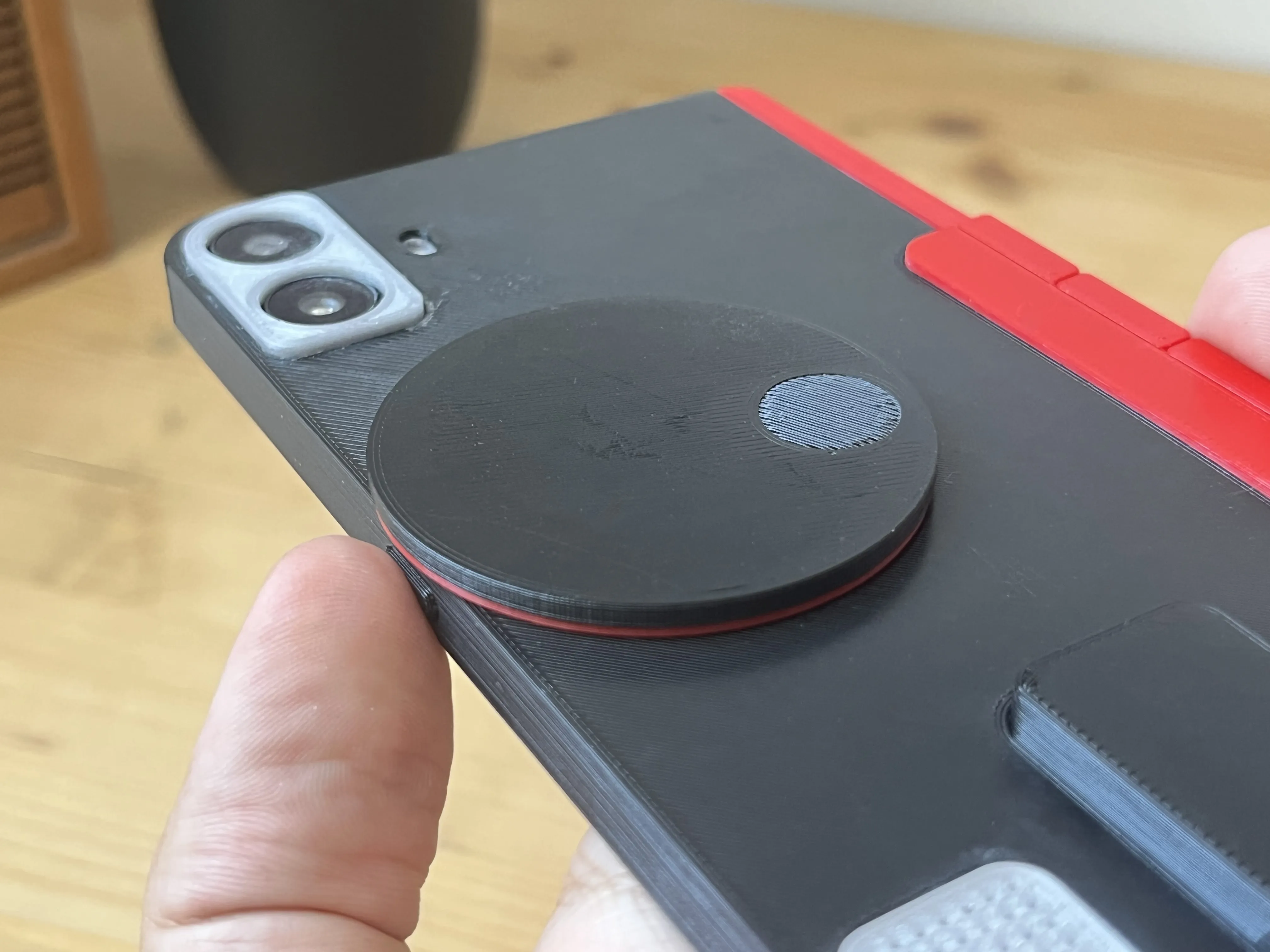
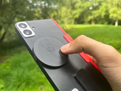
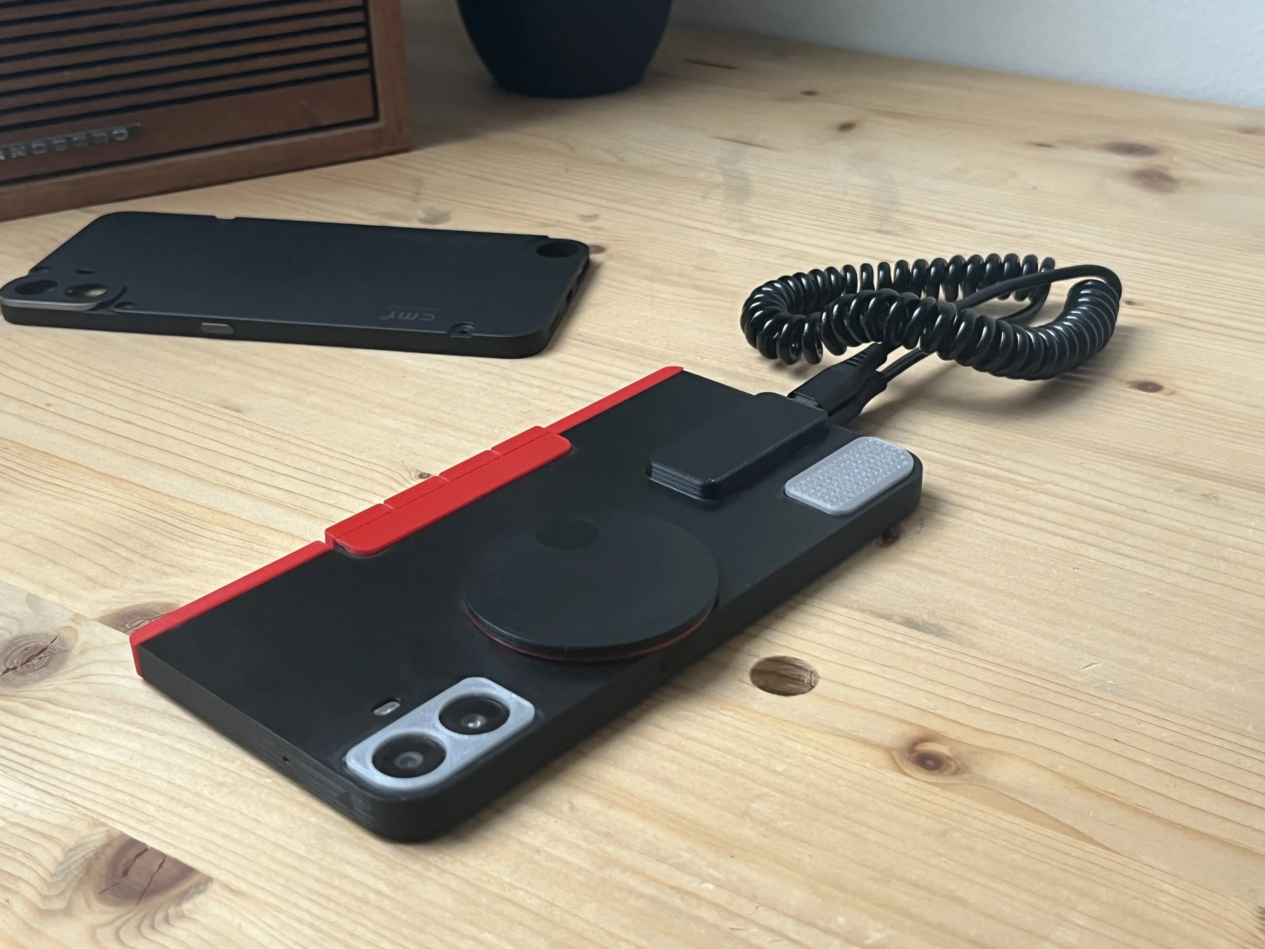
An interactive dial for scrolling, zooming, fidgeting and more…
The dial is currently just for show, and can be glued on, or left off completely. I am currently working on making this functional with a magnetic encoder, which will also attach to the Arduino. I will update these files after I get this working.
The idea would be to use the dial as a scroll wheel, for flicking through instagram … or maybe combine this with the buttons for some quick actions.
What would you use a dial for?
Construction
Components
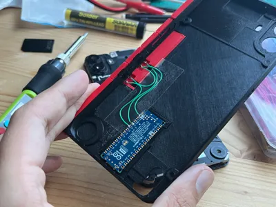
- Arduino - This model uses an Arduino Nano 33 ESP32 micro-controler to act as an input device to the phone. Other micro-controller will also work, but the ‘Arduino cover’ part will need to be modified to suit.
- Switches - 2x tact-switchs, 6mm x 6mm x 5mm, this is the standard type that you would get in your Arduino starter-kit.
- USB C - To connect to the Arduino to the phone a usb-C to usb-C cable is needed. As short as possible.
Assembly
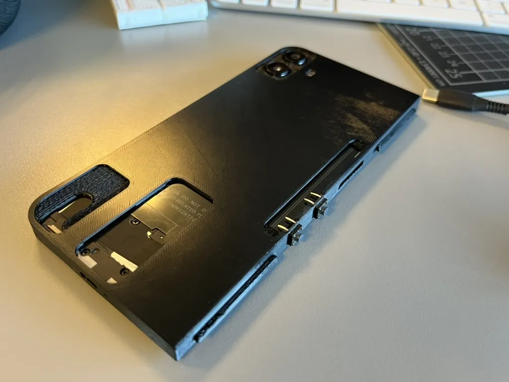
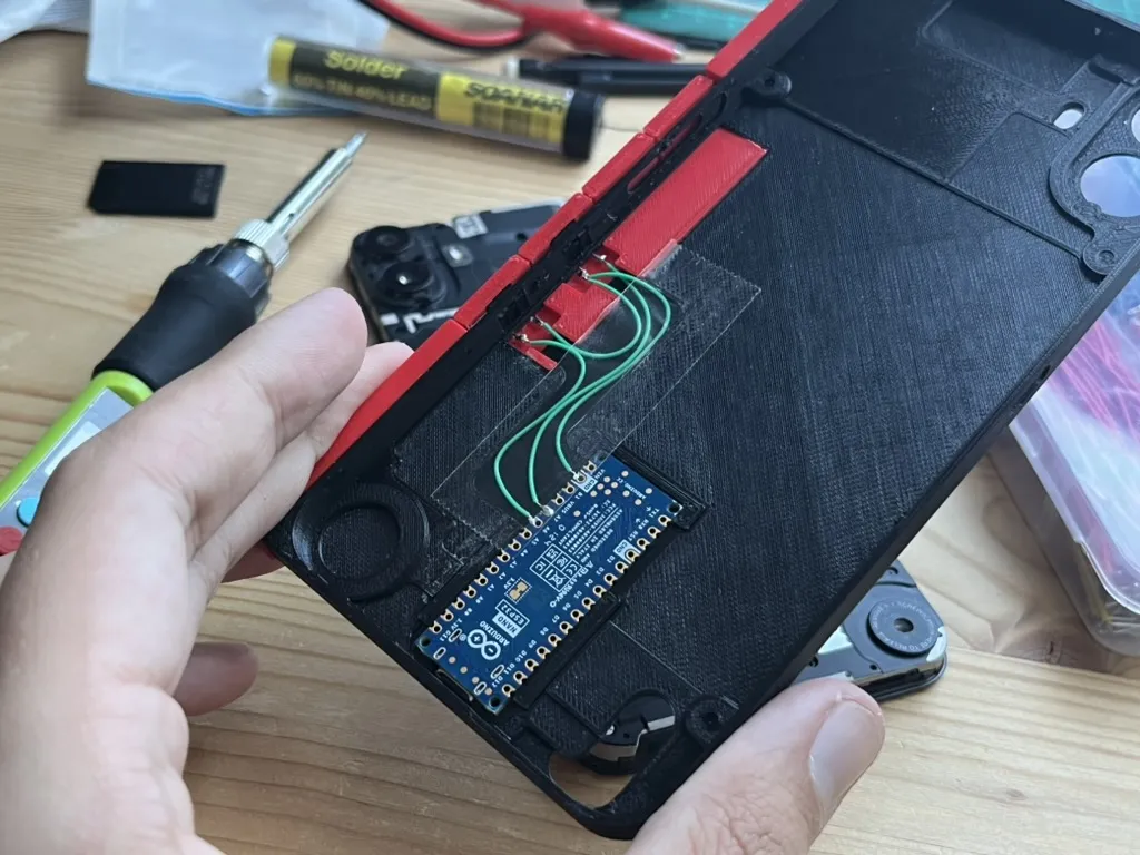
- Snip off one side of the connectors on the tact-switches, and snap them into the side of the case. The pins should poke through and be visible on the back of the case.
- Slide in, and snap down the button assembly, this should cover the tact-switches
- Slide the edge pieces onto the case, either side of the button assembly.
- Snap the Arduino into the enclosure and put it into the case from the back.
- Solder the tact-switches to the pins on the Arduino (as pictured) with very thin wire (jumper wires work fine).
- Attach the camera bezel and the speaker bezel. this might require a dab of glue.
- Position the buttons inside the case.
- Keep the sim-card tray in the phone, and slide it down into the case.
- Connect the phone to the Arduino with a USB-C cable.
Programming
Example code for the Arduino. The code emulates a USB keyboard to trigger actions on the phone.
#include "USB.h"
#include "USBHIDKeyboard.h"
USBHIDKeyboard Keyboard;
const int button1Pin = 23;
const int button2Pin = 24;
void setup() {
Keyboard.begin();
USB.begin();
pinMode(button1Pin, INPUT_PULLUP);
pinMode(button2Pin, INPUT_PULLUP);
}
void loop() {
if (digitalRead(button1Pin) == LOW) {
// Back button
Keyboard.press(KEY_LEFT_GUI); // Hold Alt KEY_LEFT_GUI
delay(50);
Keyboard.write(KEY_LEFT_ARROW);
delay(50);
Keyboard.release(KEY_LEFT_GUI);
delay(300);
}
if (digitalRead(button2Pin) == LOW) {
// Quick switch to previous app
Keyboard.press(KEY_LEFT_ALT);
delay(50);
Keyboard.write(KEY_TAB);
delay(200);
Keyboard.release(KEY_LEFT_ALT);
delay(300);
}
delay(50);
}
Thanks for looking!
<3 Louis
License



Comment & Rating (7)