
Weekdays Clock
Print Profile(0)
Bill of Materials

- Reverse Clock Mechanism x 1:
- M4 10mm Screw x 5:
- M4 Nut x 5:
- Clock face (custom) x 1:
- Bearing (ID:4mm, OD:10mm, H:4mm) x 1:
Description
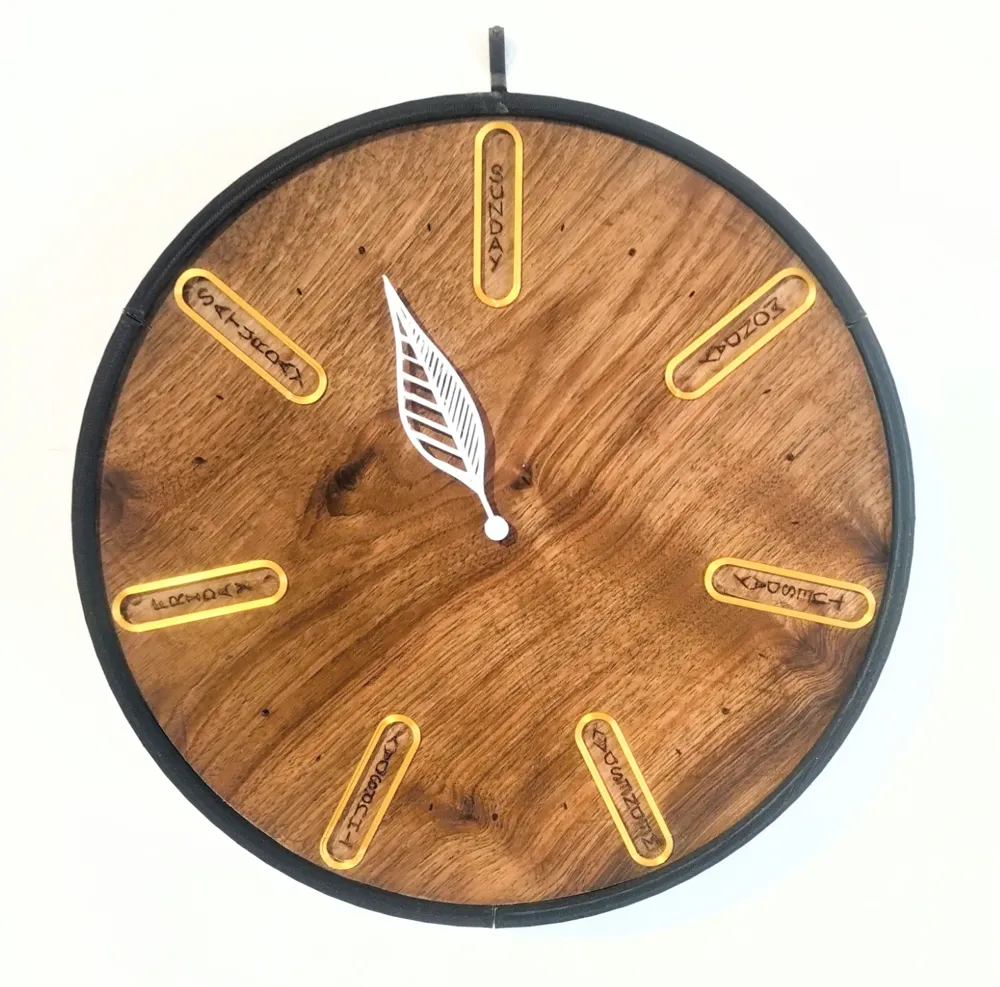
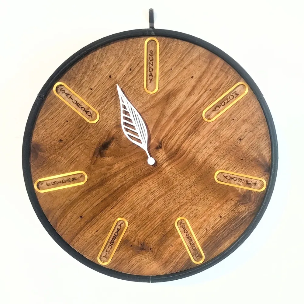
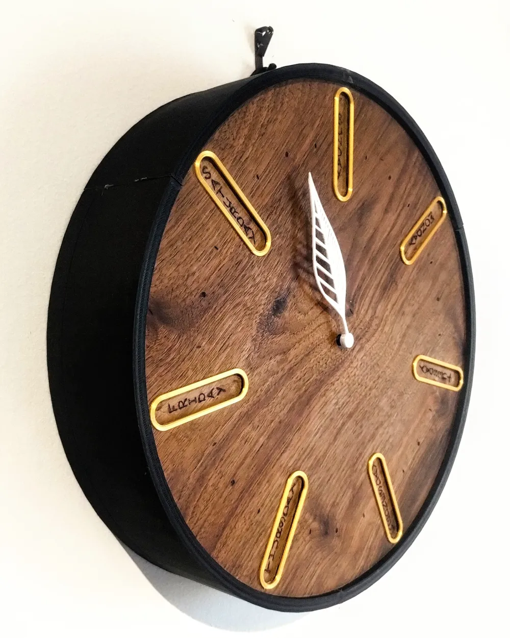
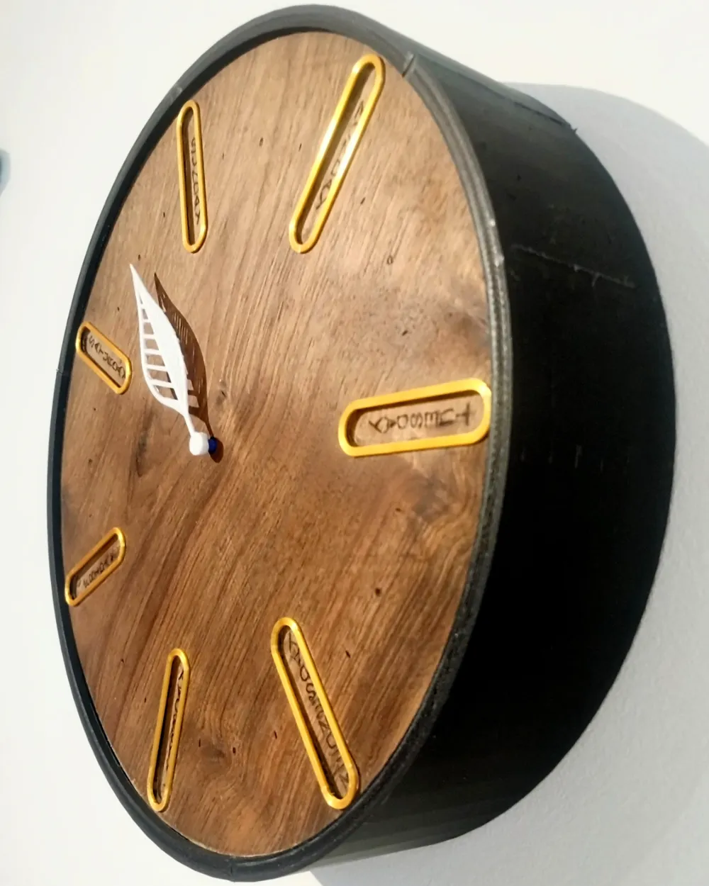
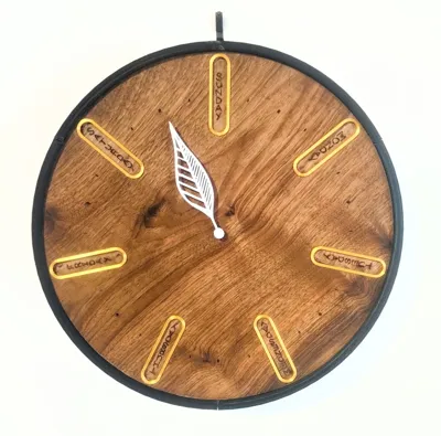
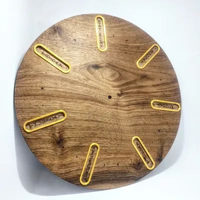
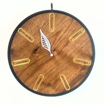
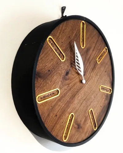
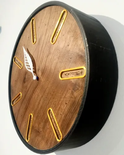
This is an analogue clock that rotates once per week, the face contains the days of the week and a singular hand.
All parts listed in the files are uploaded as STL and OBJ files, one of each is needed with a few exceptions:
Please use the drawings and images to assembly the clock.
Order of assembly should be as follows:
1) nuts placed into hexagonal groves on ‘clock sides’ (a small amount of glue may be necessary however I did not need any)
1) clockface inserted into ‘clock sides’ (hot glue around inside perimeter to keep it in place),
2) ‘battery casing’ glued securely (super glue) to gear platform',
3) Purchased reverse clock mechanism inserted into ‘battery casing’ (make sure it is battery side down so the battery lines up with the opening on the back of ‘battery casing’. I secured the nut and washer that came with the mechanism to the outside of ‘battery casing’ to keep the mechanism in place.
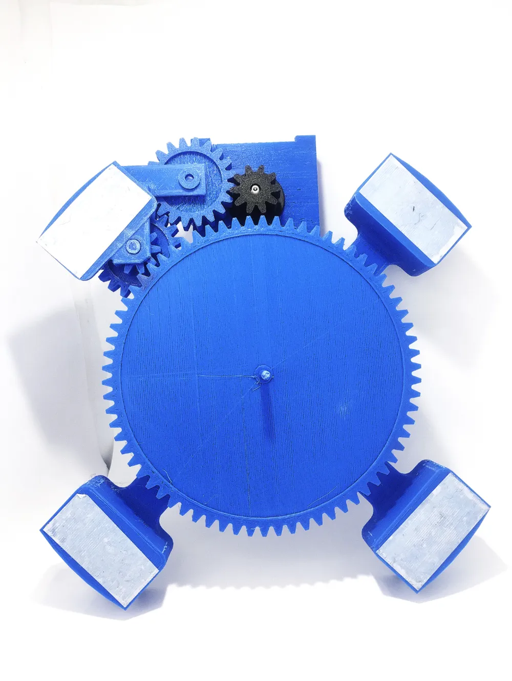
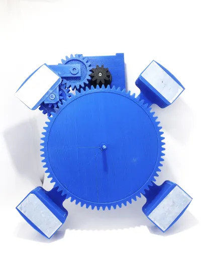
4) use ‘plug’ and ‘plug with short pin’ to secure ‘G2_20 tooth’
5) use ‘plug’ and ‘plug with long pin’ to secure ‘G3_10+20 tooth’
6) insert ‘70 tooth SECOND PIN’ through ‘G4_70 tooth’ and into ‘70 tooth PIN’ (fasten in place with a spot of glue, this could all be printed as one part but would need a large area to be supported so I chose to split it up)
7) insert ‘G4_70 tooth’ into its hole in the centre of ‘gear platform 1’
8) attach ‘G1_10 tooth’ to the HOUR HAND/CYCLINDER of the purchased clock mechanism.
9) secure ‘gear platform’ to ‘clock back’ (double sided tape or weak glue will be fine of this',
10) ‘clock back’ can be inserted into ‘clock sides’ and screwed into place.
Points to note:
- ‘Battery casing’ and ‘Gear platform 1’ should be secured together with strong glue.
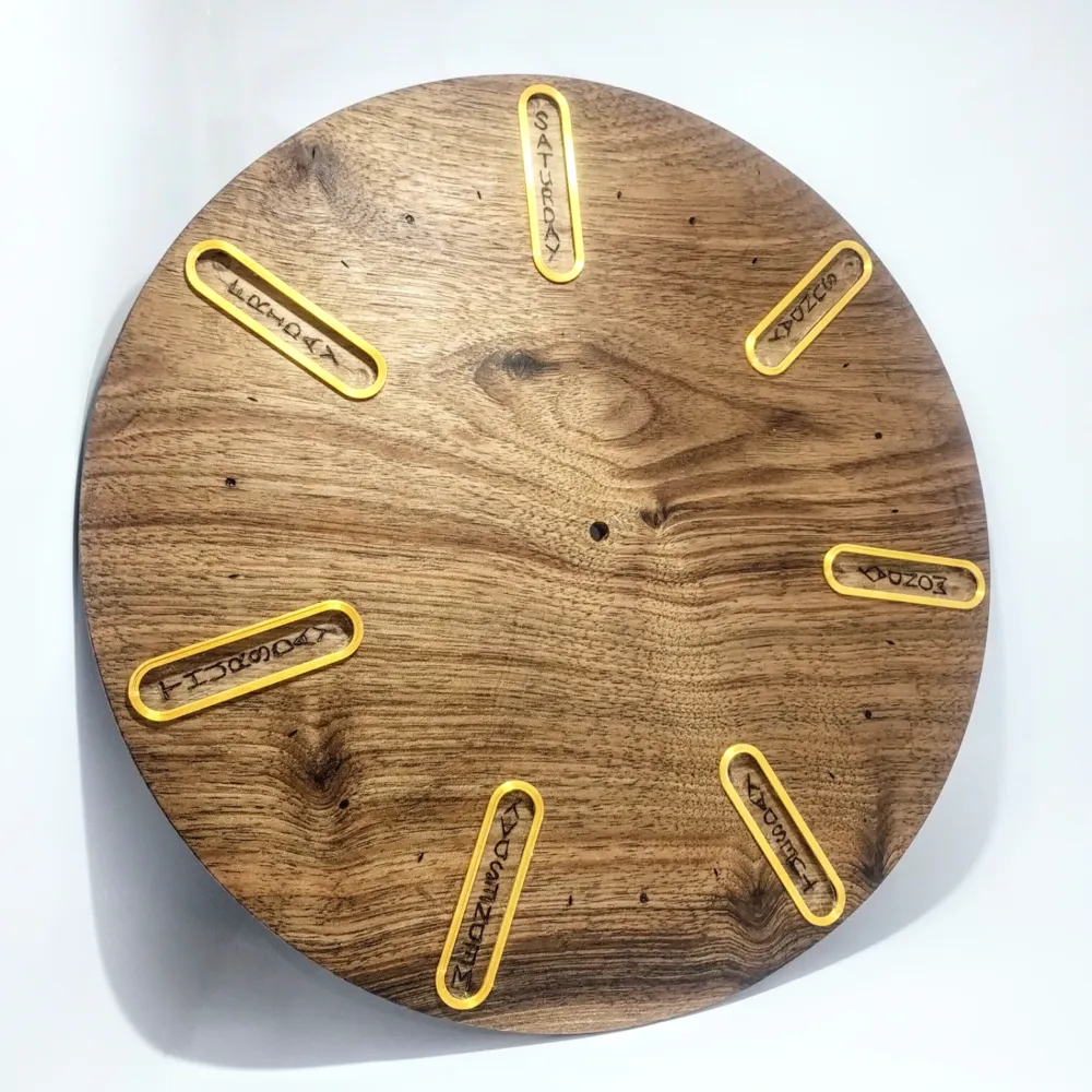
- The face is not included in this model as crafted mine out of wood. The face should be 240mm with a 5 mm hole in the centre. The days of the week should be spaced evenly around the perimeter.
- 2 of the part named ‘Plug’ will be needed
- The gear teeth have been scaled down by 0.98 as at full size there was too much friction when meshing for the weak clock motor to overcome.
- ‘Clock sides’ and ‘Clock Back’ were too large for my printer, therefore I broke them up into parts named, ‘Clock sides part 1’, ‘clock sides part 2’, ‘clock sides part 3’, and ‘clock back part 1’, and ‘clock back part 2’ and glued them together. If ‘Clock sides’ and ‘Clock Back’ fit on your printer or you scale this clock down then the broken down parts will not be needed.
- To make the clock run smoother, I added a 5mm thick ring of foam (from a packaging foam sheet) to ‘gear platform 1’ underneath ‘G4_70 tooth’ so G4 wouldn't wobble and loose alignment/meshing with G3.
- Additionally, 5 short screws (approx. 10 mm), nuts of size M4, and 4 bearings (ID: 4mm, OD: 10mm, Thickness: 4 mm), will be needed as well as a REVERSE/BARBER SHOP clock mechanism. This is imperative as the number of gears working to change the hour hand pf the bought mechanism into one rotation per week is odd.
License

You shall not share, sub-license, sell, rent, host, transfer, or distribute in any way the digital or 3D printed versions of this object, nor any other derivative work of this object in its digital or physical format (including - but not limited to - remixes of this object, and hosting on other digital platforms). The objects may not be used without permission in any way whatsoever in which you charge money, or collect fees.


Comment & Rating (1)