Elegoo Neptune 3 Pro/Plus/Max - Hemera Revo Mod - Updated Probe Height
Elegoo Neptune 3 Pro/Plus/Max - Hemera Revo Mod - Updated Probe Height


Print Profile(0)
Description
I wanted to upgrade my Neptune 3 Max to use a Hemera Revo XS with the new Revo High Flow nozzles.
I found the original model by JJR3D but I found that the probe mount was too high and it caused my nozzle to crash into the bed before the probe triggered, I also increased the size of the holes for the threaded inserts so that 5x4 threaded inserts fit correctly and I increased the recess area for the pins on the back of the breakout PCB because I found mine didn't sit flat.
I also found that the stock E0 driver on the ZNP Robin Nano v2.2 could not output enough current to power the Hemera Revo XS.
According to the documentation the Hemera Revo motor is rated for 1.33A.
To solve the issues I was having I used a BigTreeTech TMC2209 driver in the empty E1 slot and set my VREF to 1.56V.
According to the documentation from BigTreeTech the formula to calculate the is as follows

The Rsense on the BigTreeTech TMC2209 v1.2 is 100 mΩ and for a current on 1.33A the VREF would be 1.737V, a 10% margin below that voltage to prolong the driver life gives us 1.56V
I am using Klipper firmware on my Neptune 3 Max and after a lot of digging I found this github page with custom Marlin firmware for the Neptune 3 to use the E1 slot by mlee12382 which gave me the pinout for the E1 slot which is:
step_pin: PC4
dir_pin: !PA4 (I physically reversed the motor wires when I was trying to get the Hemera working with the stock firmware and needed to change the motor direction, it will most likely be PA4 and not !PA4 if you have the stock motor wiring)
enable_pin: !PC5
For the mounting plate I started by inserting 5 5x4 brass inserts (If you want to use the motor cover you need an additional brass insert in the hole on the right side of the mounting plate)

Then I attached the ABL probe using a M3x8 screw (The cooling fan points to the left and the motor points to the right)

Then I attached the Hemera to the other side of the mounting plate using 2m3x4 screws


Next I attached the breakout PCB using an M3x6 screw in the center hole and attached all of the connectors to the breakout PCB


Next using the original 3 mounting holes with M3x18 screws I attached the mounting plate to the X carriage, there is a fourth M3x18 screw that goes in the hole under the top left roller wheel.


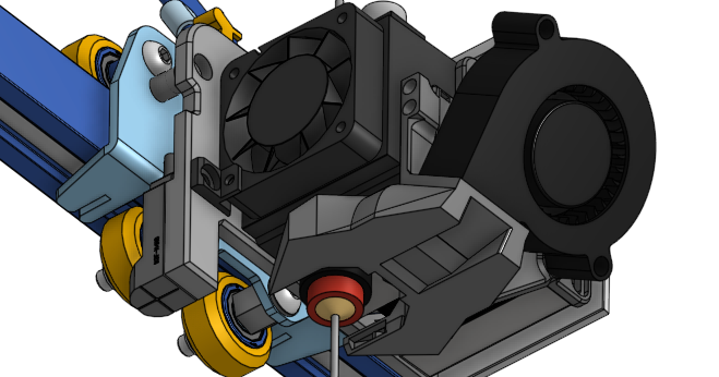
Next I put a 5x4 heated insert in the fan shroud so that the part cooling fan could be attached

I then attached the part cooling fan to the two remaining mounting holes on the right side of the Hemera motor using M3x6 screws with washers (I brought the nozzle down to the bed and then put one of the small wrenches that came with the printer under the part cooling shroud to make sure it was high enough that it wouldn't hit any prints.

For the final step I attached the 5015 part cooling fan using a M3x18 screw