
AMS Buffer Guide - Input PTFE Guide Pull Back


Print Profile(5)


Description
>>> Click Here For More Of My Designs <<<
Click HERE to check out VERSION 2.0 with CORD KEEPER
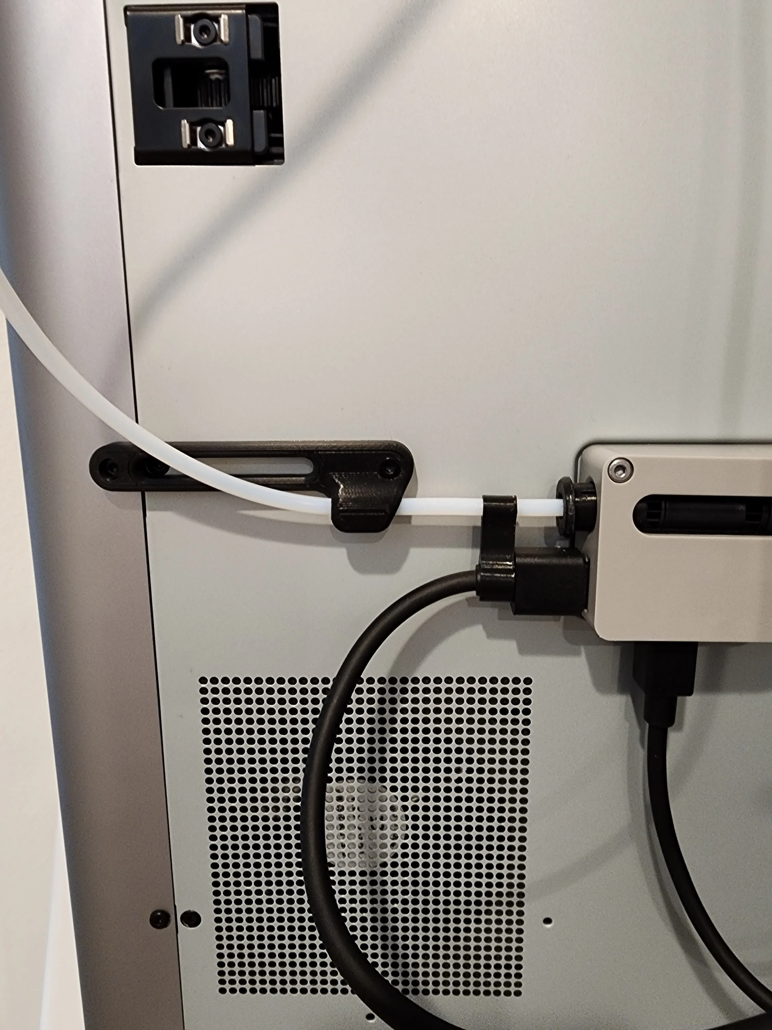
Continuing the development I started with the AMS PTFE Connecting Rod to improve PTFE tube alignment with the AMS Filament Buffer. This can be used as a standalone model to potentially reduce the likelihood of filament pull back or feeding errors and warnings. However, I recommend you use this with the AMS PTFE Connecting Rod as shown in these photos. This is a simple ten cent print and uses screws you likely already have that came with your printer.
User Feedback:
“Thank you so much for this. I was having a retract error on EVERY retract. I installed this and 300 retracts later and not one failure. Your a life saver.”
“Resolved the issues I was having with failing to pull back filament errors.”
"Printed great. Previous solution I tried didn't hold the tube securely enough."
“Does the job right”
“Printed with no problems, nice design!”
“Helped a lot!”
“Another solid design. Printed well in PETG.”
See installation guide below.
CLICK HERE TO CHECK OUT THESE OTHER PTFE ACCESSORIES
INSTALLATION:
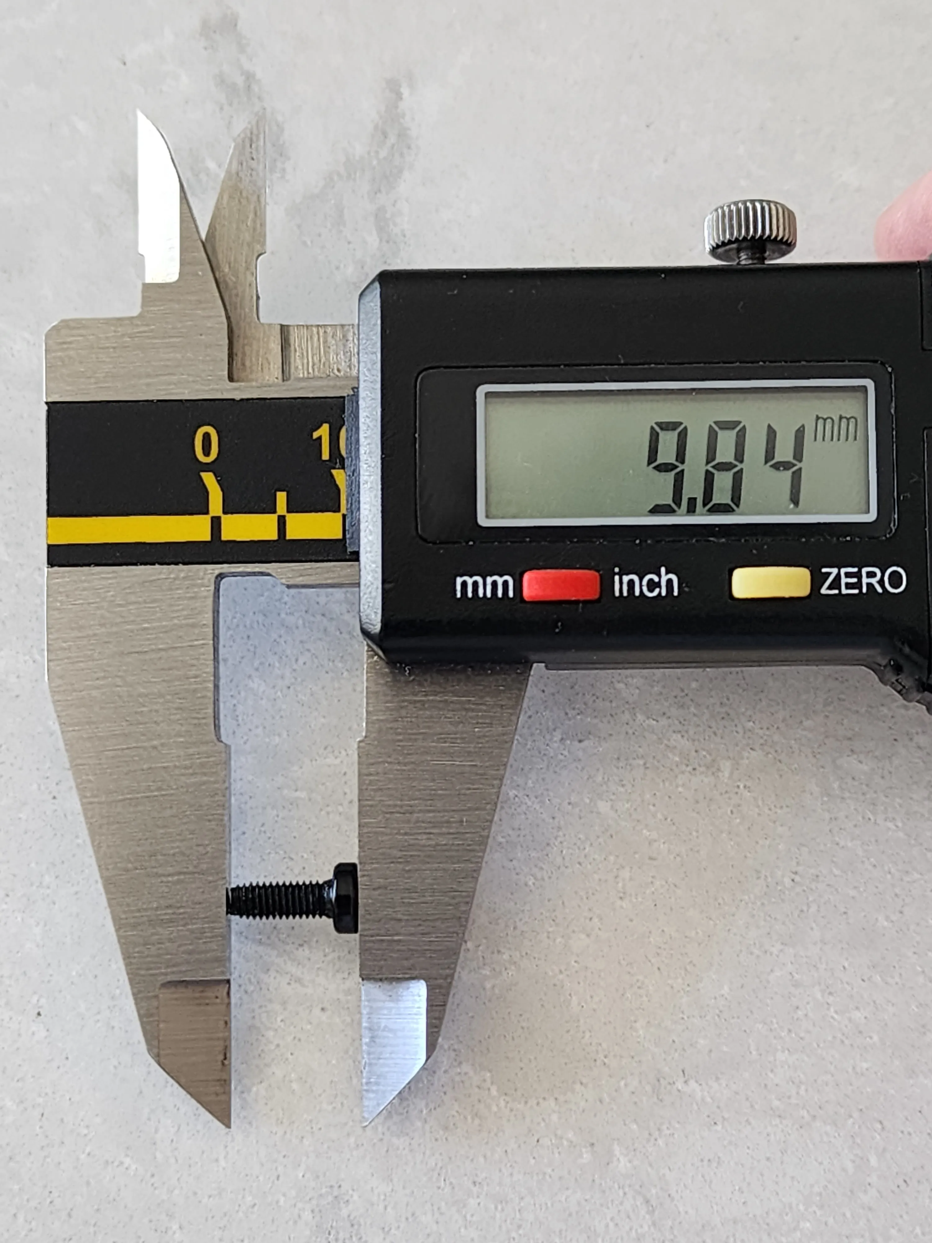
Locate and use two screws you likely already have that came with your printer. There are two of different lengths as shown below:
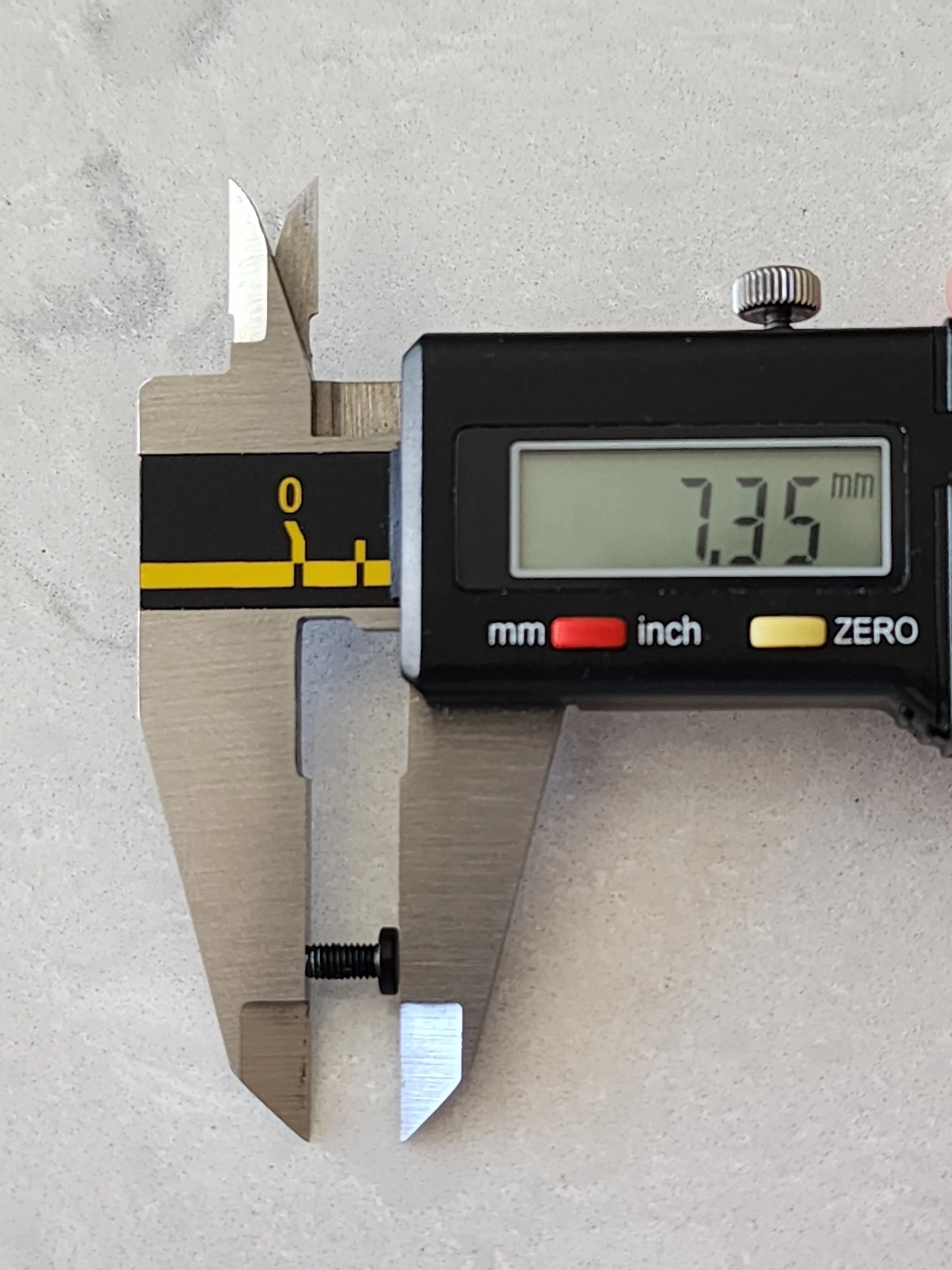
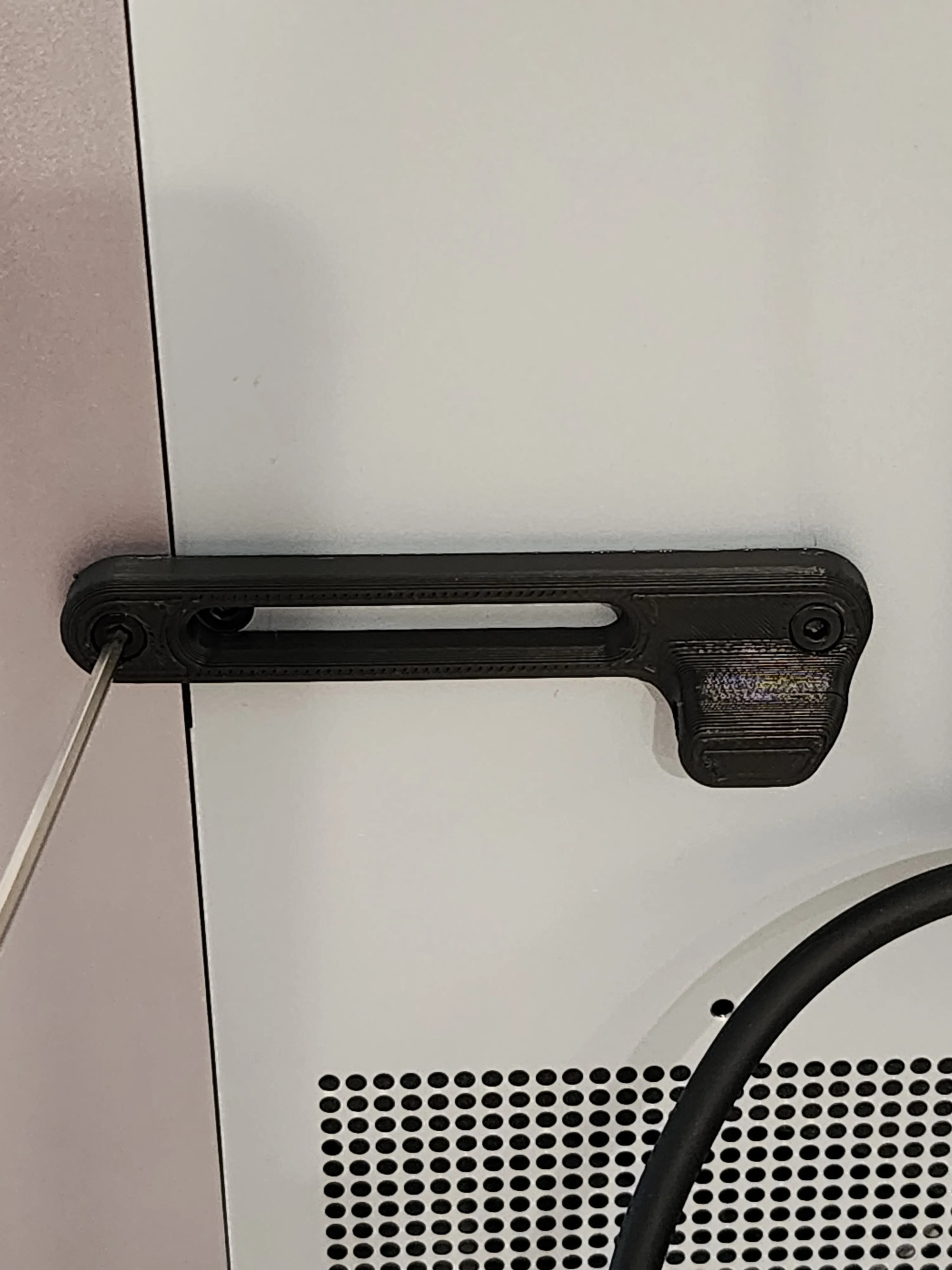
Remove the one side panel edge screw on the left, directly across from the AMS Filament Buffer and install this AMS Buffer PTFE Holder using the 7.35mm screw as shown below. Do NOT over tighten. A snug fit is sufficient:
Install the 9.84mm screw as shown below. Do NOT over tighten. A snug fit is sufficient:
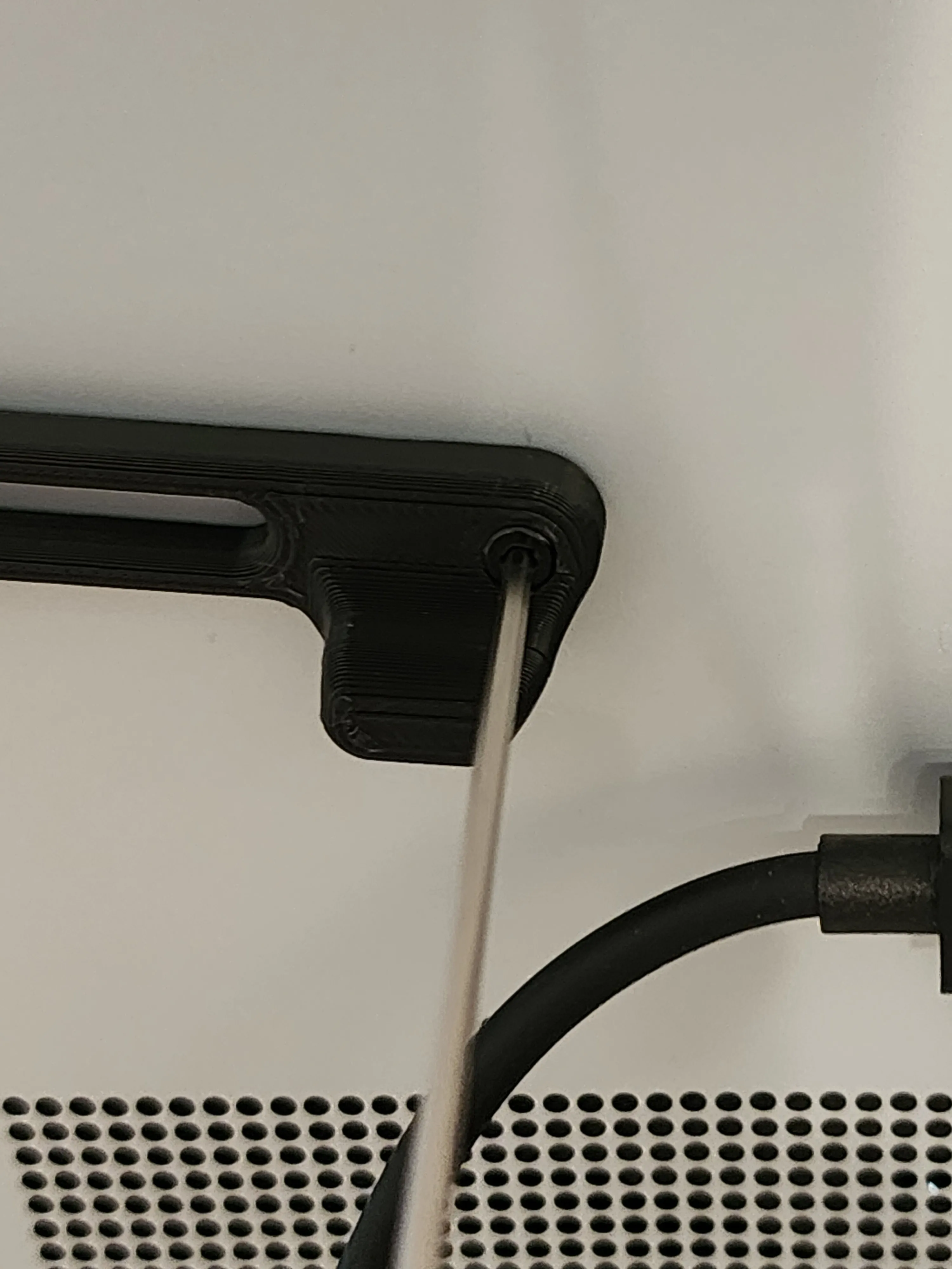
It is now installed! Now feed the PTFE tube through the AMS Buffer PTFE Holder and into the AMS Filament Buffer.
Boost Me (for free)
*** If you enjoy this model I'd be grateful if you considered a BOOST. ***
License

You shall not share, sub-license, sell, rent, host, transfer, or distribute in any way the digital or 3D printed versions of this object, nor any other derivative work of this object in its digital or physical format (including - but not limited to - remixes of this object, and hosting on other digital platforms). The objects may not be used without permission in any way whatsoever in which you charge money, or collect fees.


Comment & Rating (435)