

Print Profile(1)

Description
Description
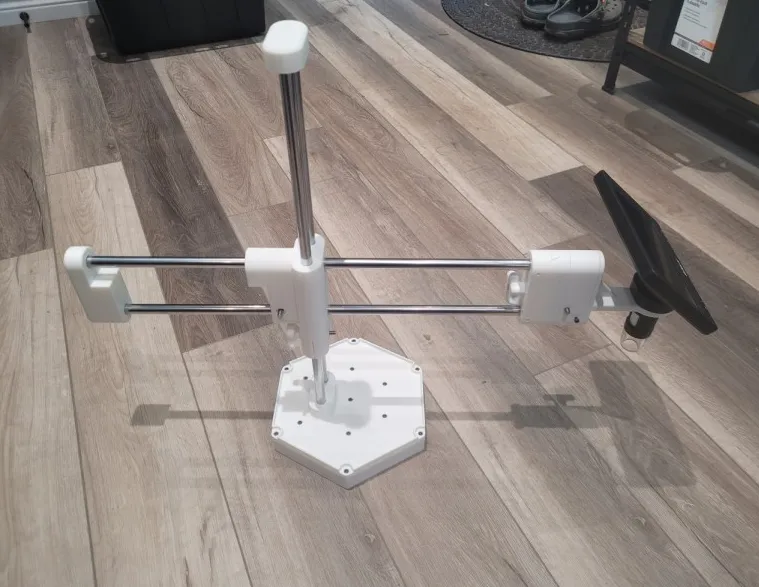
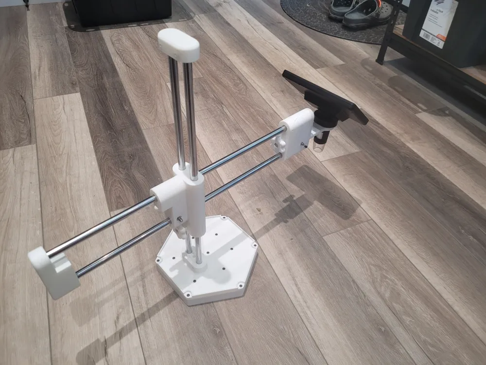
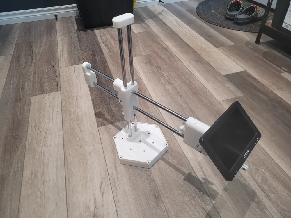
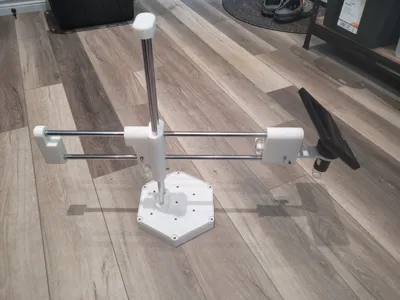
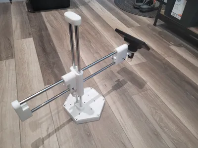
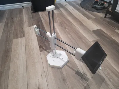
I didn't like the stand that my digital microscope came with, so I designed my own. I built this mount with this in mind. It is designed to be quite strong and easily moveable (not clamped to desk).
Note: This model only contains the stand part. Accessories are shared in a separate model. List of developed accessories:
Features
- Based around 12mm rods for good rigidity
- 195mm hexagonal weighted base to provide stability
- Lip around base cap to allow for holding small parts like screws
- Shoulder that allows for vertical and horizontal adjustment
- Accessory mount that allows for changing the attached accessory, but still retains a rigid connection
- 3D parts available for editing in my Onshape project
Non-Printable Parts
There are several non-printable parts needed
- Four (4) 12mm rods for frame. I used these, which are 500mm long. Shorter rods will work as well, but reduce the length of adjustment. Longer rods may work, but might affect stability (also depends on weight of accessory).
- Six Hundred Eighteen (618) 3/8 inch steel balls for weighing down the base. I used these, which come in a pack of 1000. You could also replace with sand or modify the base model to change the size of ball.
- Fourteen (14) M3 socket head screws for attaching base cap to base. They can be from 10mm to 20mm long.
- Eight (8) M4 grub screws or M4x12 socket head screws (or longer if you're OK with some extra screw sticking out) to lock rods onto 3D printed parts
- Three (3) M6-1.0 x 50mm hex head bolt for tightening knobs
- Three (3) M6 nuts for tightening knobs
Print Instructions
All parts can be printed in PLA with 0.4 nozzle. All parts use a layer height of 0.2mm with 15% infill (except for lower part of the base) and 2 walls loops. I've included the 3mf file.
Rod hole tolerances have been tuned to be a slight press fit for parts that don't move, and a sliding fit for the parts that need to move, but it depends on print orientation and printer tolerances. I would recommend printing the shoulder and cap pieces first to make sure they fit as expected.
Shoulder
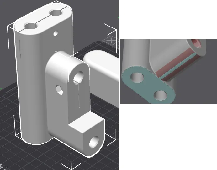
- Print with long section vertical and side protrusion laying on bed
- It would probably be OK without supports, but I painted some onto the bottom of the side protrusion to be safe (see picture below)
Side Cap
- Print with rod holes facing down
- Support needed for overhanging section. I painted them on to avoid support anywhere else (not needed for other holes).
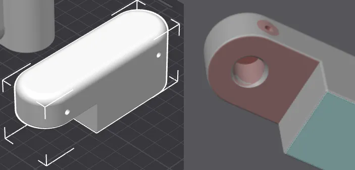
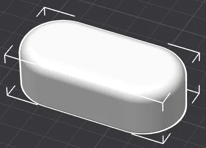
Top Cap
- Print with rod holes facing down
- No support needed
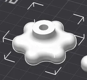
Knobs
- Three (3) knobs need to be printed
- Print with larger face on printer bed
- No support needed
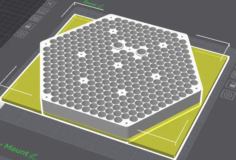
Base
- Print with holes facing upwards
- No support needed
- I modified the bottom 5mm to use 100% infill to avoid a shrinkage issue I was having (link). You might not need this.
Base Cap
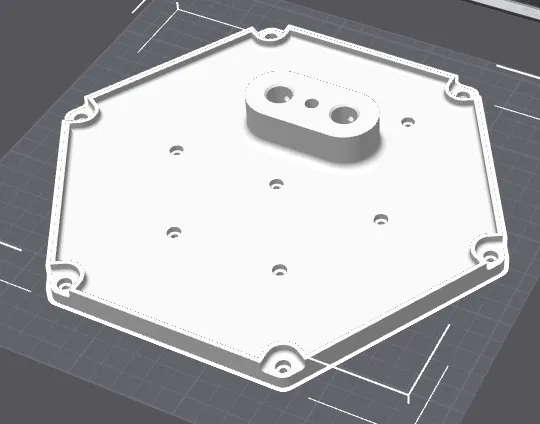
- Print with rod supports and lib facing upwards
- No support needed
Accessory Mount
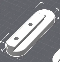
- Print with dovetail facing upwards
- No support needed

Accessory Adapter
- Print with dovetail facing upwards
- No support needed
Assembly Instructions
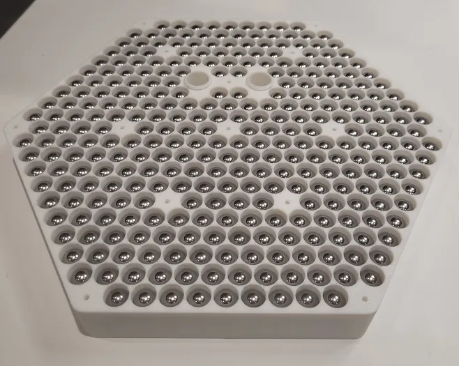
1. Add Weight to Base
Fill base with steel balls (or your choice of weight material)
2. Attach Base Cap
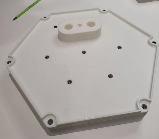
Place the base cap onto the base, making sure the rod holes line up (there is a small lip in the base rod holes to help with alignment).
Fasten base cap onto base using M3 screws. They should self-tap into the base, but don't over tighten to avoid stripping the threads. The top of the cap head should recess into the base cap. Don't forget the screw in between the rod holes.
You could probably don't need all screw locations, but I wanted to make sure there was no base cap flex in the final product.
3. Attach Vertical Rods
The two vertical rods should press down through the cap and into the base. Make sure they are both pressed down before locking them.
Lock the rods onto the base cap using M4 grub screws or M4 cap head screws. The holes are sized so that the screws will self-tap. Avoid over-tightening to prevent stripping the threads.
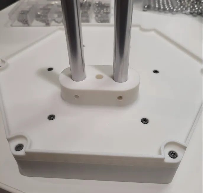
4. Assemble Shoulder
The shoulder uses slits in the part along with bolts and nuts to tighten the shoulder onto the rods.
Assemble the knobs by pressing the hex bolts onto the 3D printed knob heads and making sure the hex head is fitted into the cutout firmly. It should be a tight fit to prevent movement.
Place M6 nuts into the two locations in the shoulder, one at the bottom of the long vertical section, opposite the side protrusion, and one on the side protrusion, close to the lower horizontal rod.
Push the knob screws through the part and screw into the nuts. There should be one knob on the right side of the shoulder for tightening onto the horizontal rods, and one knob on the read of the shoulder for tightening into the vertical rods.
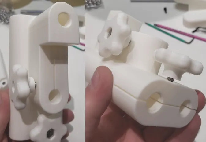
5. Assemble Shoulder and Top Cap
Slide the shoulder onto the vertical rods and test to make sure the tightening know works.
Press the top cap onto the top of the vertical rods to prevent the shoulder from sliding off. Make sure the rods are fully inserted into the cap before locking.
Lock the rods into the top cap using M4 grub screws or M4 cap head screws. The holes are sized so that the screws will self-tap. Avoid over-tightening to prevent stripping the threads.
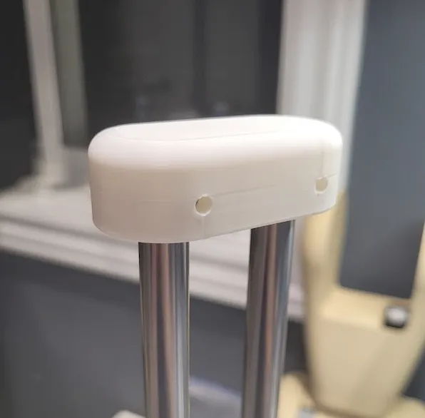
6. Assemble Horizontal Rods and Side Cap
I find it easier to first assemble the rods into the side cap and then slide the assembly into the shoulder. Make sure the rods are fully inserted into the side cap before locking.
Lock the rods into the side cap using M4 grub screws or M4 cap head screws. The holes are sized so that the screws will self-tap. Avoid over-tightening to prevent stripping the threads.
Slide the two rods and side cap into the shoulder so that the side cap profile fits into the shoulder side protrusion. It should be able to slide all the way in with the two parts fitting together.
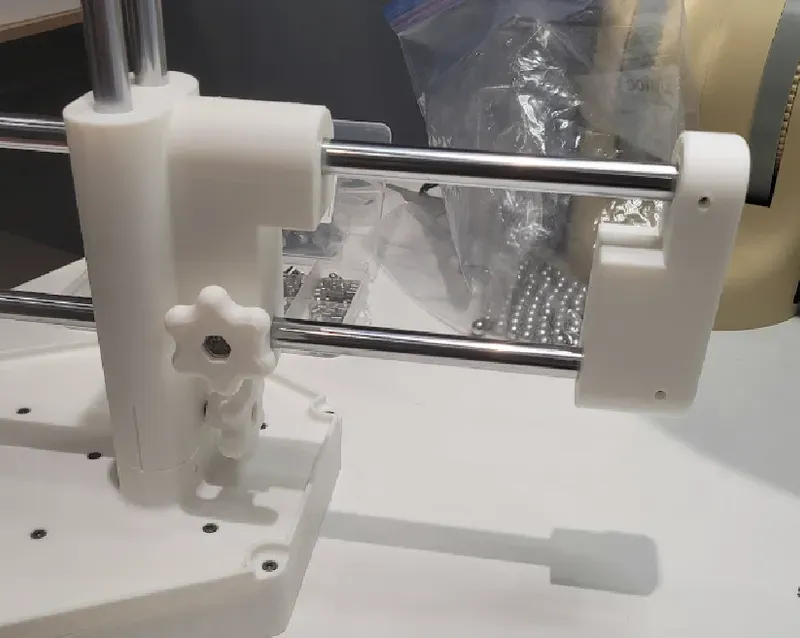
7. Attach the Accessory Mount
The accessory mount acts as the opposite cap for the horizontal rods. Attach in the same way as attaching the side cap, with both rods inserted fully and using M4 screws to lock rods in place. Make sure the dovetail is oriented so that the open side is to the top (accessories slide onto the mount from the top).
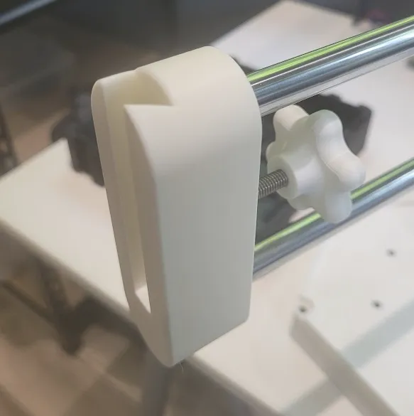
8. Assemble the Accessory Adapter
The accessory adapter is tightened onto the accessory mount using a knob.
Place a M6 nut into the adapter and slide the adapter onto the mount. The dovetails should align so that the side profiles match.
Assemble a knob in the same way as the shoulder tightening knobs and press it through the hole on the rear of the mount and screw it in the nut. This should lock the adapter in place, but allowing for easy removal and swapping accessories.
The adapter contains two M3 holes, sized for self-tapping, to attach accessories to.
Future
There are a few changes I may make in the future
- Add nut inserts in places where self-tapping screws are used to fasten down shafts. I'm always afraid of stripping the threads when tightening these screws, so a slot that you can put a nut in would avoid this
- Improve horizontal rod tightening in shoulder to allow for stronger tightening
- Create an accessory for holding a camera using a ¼"-20 screw
- Add cable clips to support wired accessories
License



Comment & Rating (3)