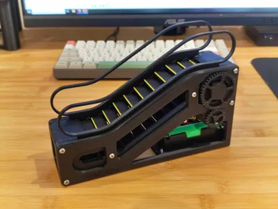
Motorized Escalator Model - Redux


Print Profile(2)


Bill of Materials

Description
This is a reworked version of my motorized escalator model. Similar to the updated version of the non-motorized escalator, this model incorporates a bunch of improvements to greatly simplify assembly and increase the smoothness of the mechanism.
For a version that doesn't require soldering and uses Maker Supply parts, check out this version: https://makerworld.com/en/models/589146#profileId-510496
Materials
Hardware
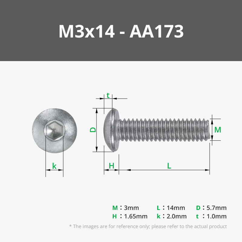
- 10 M3x14mm bolts (can substitute these for longer bolts, within reason)
- 9 M3x10mm bolts (can also substitute these for longer bolts)
- Wires
- Double sided tape (for electronics)
Electronics
- N20 geared motor, 30RPM 6V
- DPDT 3-position On-Off-On toggle switch
If using an 18650 battery:
- TP4056 battery charging board or similar
- 18650 battery and holder
If powering directly from USB:
- USB C or Micro USB breakout board
Printed parts
- 30 steps
- 60 chain links
- 2 end caps
- 1 left outer track guide and 1 right outer track guide
- 1 left inner track guide and 1 right inner track guide
- 1 left handrail and 1 right handrail
- 1 spindle
- 1 drive-side sprocket and 1 non-drive-side sprocket
- 1 motor pinion
- 1 motor clamp
- 1 bottom cover
Assembly
Please reference the non-motorized escalator assembly video to put together the main mechanism:
Electronics
Use the following diagram to wire up the 3 position switch (source):

Once the switch is wired up, connect one pair of wires to the motor.
If using a battery, connect the other pair of switch wires to the output pins on the battery charging board, and wire up the battery holder wires to their respective pins.
If powering directly from USB, connect the switch wires to the 5V and GND pins of the USB breakout board.
Final assembly
- Place the motor in its slot on the right outer guide. Secure it using the motor clamp and 2 M3x14mm bolts.
- Mount the switch in the hole on the left outer guide, and secure with a nut.
- Use double sided tape to attach the USB charging or breakout board to the bottom cover, with the port lined up with the slot on the left side.
- If using a battery, attach the battery holder to the right side of the bottom cover using double sided tape.
- Mount the bottom cover to the underside of the chassis with 4 M3x10mm bolts.
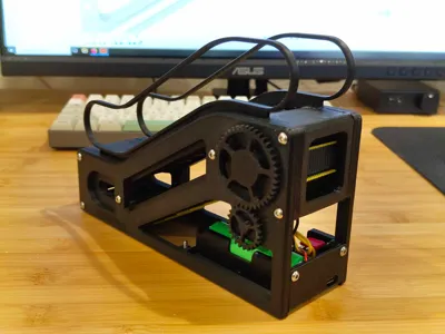
- Press the motor pinion onto the motor shaft, and ensure that it meshes with the main spindle gear.

Comment & Rating (39)