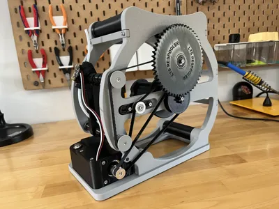
LTS Respooler V1.5, Motorized Filament Winder
LTS Respooler V1.5, Motorized Filament Winder


Print Profile(7)
Description
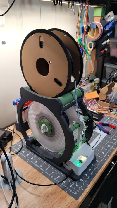
This Design is inspired by the awesome V-Spooler and takes the same basic approach to respooling your Filament Spools! My Design is even more compact and incorporates a Steppermotor and a Filament runout sensor for ease of use. In my experience, it works great!
The Respooler needs quite a few non-3D printed parts. Visit my Shop to buy different kinds of Hardware Kits to make sourcing easier! I also offer a simple PCB for more organized Electronics :)
Changes for V1.5:
- new Electronics Case geometry for easier printing/less supports/better cooling
- new Base plate for less supports
- more secure Filament guide Lid attachment
- Split entire build into more Print Profiles
Changes for V1:
- Motor mount now adjustable
- reduced amout of supports needed
- improved tolerances between parts
- Updated Arduino Code
Needed Hardware and Electronics:
- Hardware (pdf) and the Arduino Code can be found under Documentation
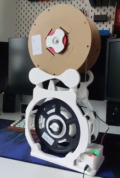
How to use it:
- Feed the Filament from the top Spool through the PTFE tube
- The right LED will light up; without Filament, the Motor does not start
- Attach the Filament to the bottom Spool (i recommend this model) and press the Push Button
- Once all the Filament has been transferred, the motor will automatically stop and you can manually remove the Spool
- If you want to interrupt the winding, just press the Button again
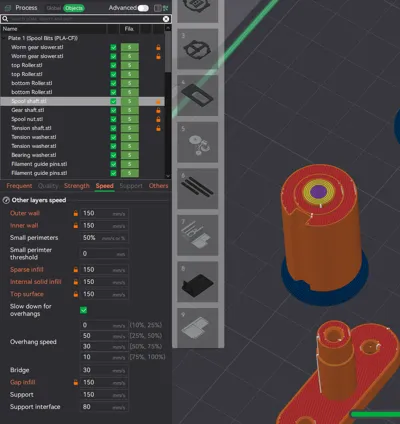
Basic assembly and printing notes:
- PLATES 2, 3, AND 4 GO OVER THE PURGE LINE! Please pause before the first layer to remove it
- the screws thread right into the plastic (no inserts), don't over-tighten them!
- it is best if the black parts are printed with a durable filament, i recommend PLA-CF
- some parts use supports that need to be removed
- The screws are not pictured in the Assembly Guide
Hardware Kits:


Assembly:
The next few steps can be skipped if you ordered the Power Pack.
Start with the Motor Base plate. |  |
Slide in the NEMA 17 stepper motor and secure it using (3) M3 x 6 srews. This can be fairly loose as the exact position needs to be adjusted later.
Insert (4) M3 nuts into the hexagonal holes and push them down. |  |
If you bought it, you can now Install the PCB using (3) M3 x 6 screws.
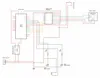
If you do not own the PCB, skip this step. You can find a wiring Diagram in the Documentation. |  |
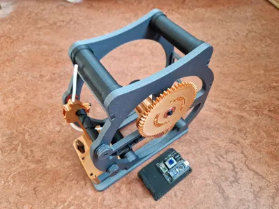
Install the Arduino Nano and the stepper driver onto the PCB and connect the steppermotor.
Make sure the driver is installed in the correct orientation.
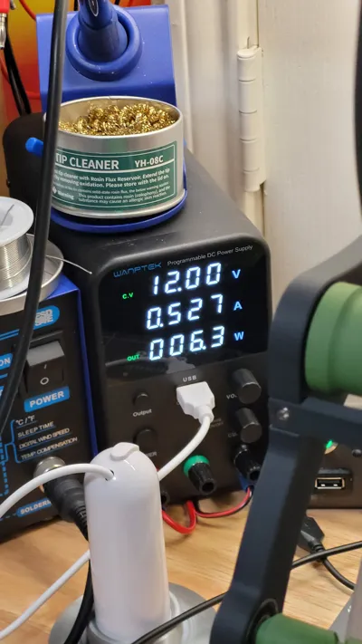
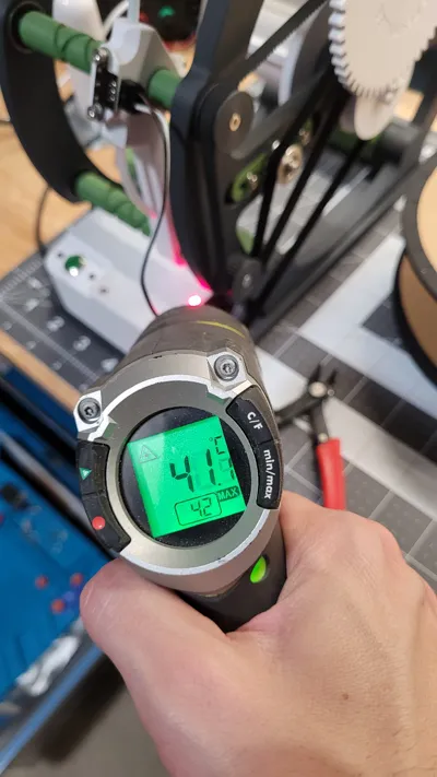
The Power regulator screw should face roughly the same direction as in the picture. If the Motor is to weak, please adjust the screw!
If the Motor is jittering and not spinning correctly, please try swapping out the two inner wires. |  |
Take the Interface and install The Button and the LEDs. The LEDs will need a little glue to stay in place.
Solder wires to the Button and LEDs and connect the other ends to a female dupont connector. The correct order is written on the PCB.
Please use flexible/small gauge wire, space inside of the case is very limited! |  |
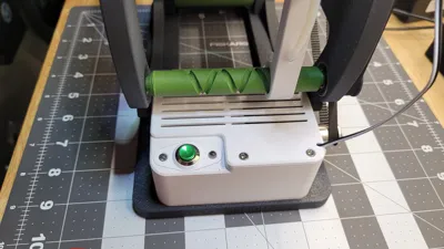
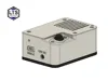
Set the Electronics case onto the Base plate and secure it from below with (4) M3 x 6 screws.
Connect the Interface to the connectors on the PCB and push it into place.
If you are using an arduino with mini USB, you can find a print profile for an alternative Case!
If you are wiring everything yourself and don't need the USB port, there is a print profile for the Case without it! |  |
Connect the Filament Sensor to the PCB. The switch needs to be in a “normally open” configuration. You only need two of the tree wires. Usually, you can remove the red wire.
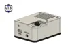
With all the electronics in place, close the Electronics case using (4) M3 x 6 screws. The wire for the Fiament Sensor is routed through the little slot in the lid.
You can now connect the arduino to your PC and upload the code found in the Documentation. |  |
| Attach the pulley to the Motor and screw the Power Pack down to the Base using (4) M3 x 10 screws (from below). |  |
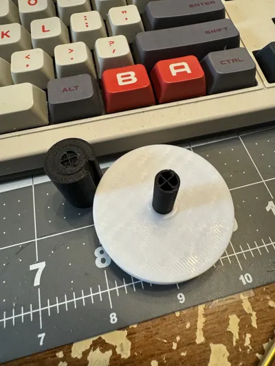
| Take the Spool center and insert the Spool shaft into it. Secure it using a M3 x 10 screw. The hole is not pictured here, it's located on the left. |  |
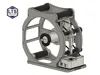
Remove all the Supports from the Frame R and press (4) bearings into their position.
Two of them are installed front/left and the other two on each side of the center shaft. |  |
Push the Spool shaft through the two central bearings as seen on the picture.
Slide the Spool shaft washer onto the shaft. (Seen on the picture as the small white ring around the center shaft)
You can also screw on the black Spool nut now. |  |
| Attach the small Gear and secure it with a M3 x 10 screw. |  |
| Push in the Gear shaft and secure it using (2) M3 x 10 screws and (2) M3 nuts (on the other side. |  |
Attach the Tension shaft as shown in the Picture and secure it loosely with (2) M3 x 10 screws.
Don't forget to add the washers (pictured in red) and the (2) M3 nuts on the other side.
The black piece should be able to move side to side. |  |
| Attach the GT2 Pulley with an M3 x 6 screw (screw not pictured). |  |
| Take the Filament guide and insert two PTFE tubes as seen in the picture. (this might take a bit of force) |  |
| Insert the two worm Gears as pictured. |  |
| Slide in the two Filament guide pins. They are red in this picture, you might need to spin the worm Gears a little to wiggle them into place. |  |
Close the holes using the Filament guide lids and secure them using one M3 x 6 screw each.
V1.5 has little hooks attached to the Filament guide to secure the lids more safely |  |
| Slide the two shafts of the worm Gears through the corresponding bearings on the right Frame. Attach the two Filament Guide Pulleys and secure them with one M3 x 6 screw each. |  |
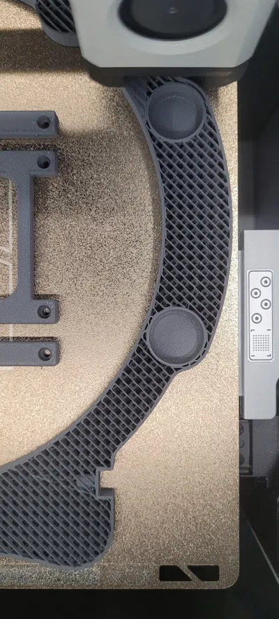
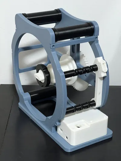
| Press the (8) bearings into the ends off all four Rollers. |  |
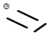
| You can now slide the Rollers into position. The longer ones are on top. |  |
| Add the left Frame L. The fit is pretty loose at this point. |  |
Attach all three Braces between the two frame sides using (8) M3 x 10 screws. |  |
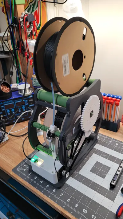
Add the 400mm Belt (red).
Press the remaining bearing into the big Gear slide the gear, together with the 430mm Belt, into position.
Secure The gear with a M3 x 6 screw and the Gear washer.
!! make sure the two worm gears are in sync, meaning they're both at the same angle/position !!
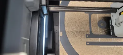
If needed, you can now adjust the belt tension. |  |
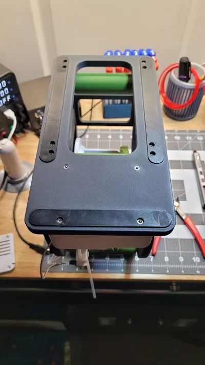
| You can now lower the Frame onto the Base and secure it from below with (8) M3 x 16 screws. Make sure the surface where the Base connects to the Frame is reasonably smooth. |  |
Connect the Frame to the Motor Base with (2) M3 x 10 screws! (one on each side)
This step is important because otherwise the belt might start skipping even at low resistance. |  |
Now, connect the 400mm Belt to the Motor shaft.
You will have to unscrew the motor Pulley and slide it onto the shaft together with the Belt.
Adjust the belt tension by loosening the three screws that hold the Motor. You can now slide the Motor to the left/right and tighten the screws again. |  |
| Insert the 4mm steel ball into the hole of the Filament guide. |  |
Remove the metal lever from the Filament switch and slide it into position as seen on the picture.
Secure it with (2) M3 x 6 screws. |  |
| If you want, you can now glue the TPU or Foam Feet into position. |  |
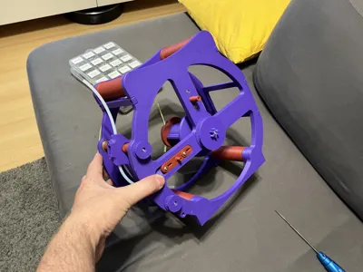
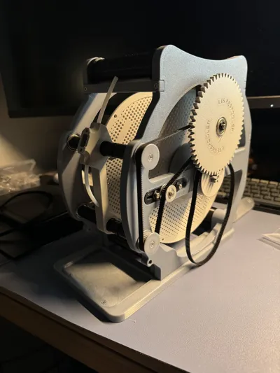
| And with that, your Respooler is complete! :) |  |
Documentation (3)
Comment & Rating (147)