espCam security camera (also for print monitoring)


Print Profile(0)
Description
About
The espCam is an enclosure for the ESP32 CAM microcontroller. The camera is designed to be a small good looking security camera that can also be used to monitor prints. It features a ring light with diffuser that is an improvement over the built-in LED. It also has an optional wifi antenna to increase connection stability and range compared to the built-in one. To maximize the amount of mounting possibilities it is compatible with the popular Articulating Raspberry Pi Camera Mount by @Sneaks.
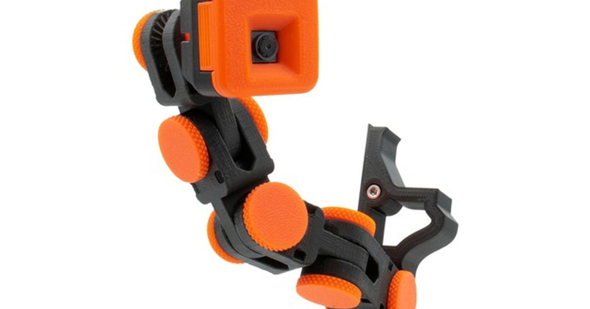
Renders


The camera features a dimmable LED ring that can turn on when motion is detected.


The camera makes use of the very popular Articulating Raspberry Pi Camera Mount
by @Sneaks.

Print settings
I recommend printing with 3 walls and 20-25% infill.
The case and LED holder have to be printed using supports, the other parts can be printed without. I would recommend using tree supports for the case and regular supports for the LED holder. The parts have already been placed in their optimal orientation. For the best results I recommend printing the diffuser at 0.1mm layer height and the other parts at 0.15-0.25mm.
Bill of Materials
Filament
In total the printable parts use around 50g of filament. It doesn't really matter what material you use.
Electronics
It uses an ESP32-CAM module with the OV2640 camera as well as the ESP32-CAM-MB (they can most of the time be found as a bundle on Aliexpress and shouldn't cost more than €5-10).
An optional wifi antenna can be used for an extended wifi range (often this is also found in the same bundle as mentioned before).
For the lamp, a LED ring with an outer diameter of 52mm of type sk6812 or ws2812b is required.
Screws
Just two m3 SHCS screws are needed with a length of 6-10mm.
There are also two heat-set inserts required, I accounted for the ones from Ruthex, they require a hole with a diameter of 4mm and a depth of 5.7 but other brands would also work.
Other
You will need some wires to connect the LEDs to the ESP32 module.
Finally you will need a micro USB cable to power and control the ESP32 module.
Printed parts
| Name: | Amount: | Notes: |
| Case_(Antenna) | 1 | Choose “_Antenna” when using an external wifi antenna |
| Bracket | 1 | |
| LED-Holder | 1 | |
| LED-Diffuser | 1 |
Assembly
1) Heat-set inserts
The only part that needs heat set inserts is the bracket and they can be installed with a soldering iron in the places shown in the picture below.

2) Preparing the electronics
The first step is to solder the cables to the LED ring. You will have to connect a 10cm cable to the 5V, GND, and Data In pin, try to give them a different color wire to make it easier in a later stage.
Note: Make sure that the led ring will still fit between the LED-Holder and the Bracket as shown in the second step of part 3.


In order to get a 5V input to our LED ring we will have to move the 0 Ohm resistor from 3.3V where it is placed by default (circled red in image) to 5V (circled green in image).
If you will be using the optional wifi antenna the resistor shown in the picture also has to be moved from the red to the green circle.
3) Assembling the housing

Insert the LED ring into the holder and make sure that the contact pads with the wires attached are in the same orientation as shown in the image above.
If you are using an external wifi antenna feed the wire through the square hole shown on the right side of the image below and plug it into the esp32's connector. Once this is done put the esp32, connected to the motherboard in its bracket with the charging port facing toward you and the camera going through the hole in the bottom.

Put the wires through the corresponding hole in the bracket and click it into place.
Now it is time to connect the wires from the LED ring to the esp32. You will need to solder the cable connected to 5V to the VCC pin on the esp32 (pin 5 from the top on the left row). Connect the cable connected to ground to the GND pin (pin 2 from the top on the right row). Finally, the cable connected to Data In can be soldered to GPIO12 (pin 3 from the top on the right row).
If you are not sure which pin is which you can check out the pinout here: https://randomnerdtutorials.com/esp32-cam-ai-thinker-pinout/

If you are using the wifi antenna the other end of the cable can now be screwed into the appropriate hole in the case.
Once that is done the assembly can be put into the case and screwed in from the back.

Finally, the diffuser can be put into place, it is designed to be friction fit but if that doesn't work you can use a little bit of glue.
4) Programming
For programming the esp32 I would recommend watching this video from @MaxImagination on Youtube. Additionally, you will also need to install the neopixel library from Adafruit in Arduino IDE.
Note: In order to get the LEDs to work you will have to use the code attached instead of the one directly from Git Hub. If you want to use the one from Git Hub because it is a newer version you can copy the part about LEDs on the peripherals.h tab to it (here you can also change the color of the light if you wish to do so, the brightness can be controlled through the digital environment).