Wireless powered Bento Box Air Purifier for X1C / P1P

Remixed by

Wireless powered Bento Box Air Purifier for X1C / P1P

Remixed by
Boost
102
204
27

Print Profile(1)

All
X1 Carbon
P1S
P1P
X1
X1E
A1

0.16mm layer, 2 walls, 10% infill
4.2 h
3 plates
4.9(12)

Boost
102
204
27
2
205
165
Released

Description

The content is too long and has been truncated

UPDATES:

  1. April 7th: Added support for 24V 4020 fans on V2 design (should also work for V1 designs). If using 24V fans, trim the boost converter output to 24.0 instead of 12.0
  2. April 7th: Added “wireless test jig” to help with assembled coil testing before installing the enclosure. Simply mount the transmitter box into the allotted space and align the receiver box on the debossed corner. The receiver coil should be over the non-perforated region of the base.


WIRELESS POWER:

The major change here is that I added an wireless receiver module to the bottom of the assembly coupled with a wireless transmitter module for installation under the unit. Alignment between the receiver and transmitter was determined via a 3D scan of the X1C and should be as close to perfect as you can get in X, Y, and Z (z-distance matters as much as X and Y).

Everything is magnet or friction fit installable and requires no modification to the printer housing. Power is supplied via an external micro-USB port and the instructions provide parts for a completely solder-free assembly.


V2 BENTO BOX

Printed Parts

Fan Duct 6x3 magnets or Fan Duct 4x2 magnets
Receiver Box 6x3 magnets or Receiver Box 4x2 magnets
Wireless Transmitter Box
Wireless Transmitter Cover
(OPTIONAL) Wireless Test Jig

(From Bento Box Creator)
Cover_voronoi or Cover_hemp
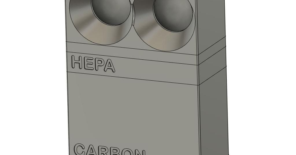
Hepa
Carbon
Fan case
CMag Case 01
CMag Case 02
4x net_infill
BentoBox20 User Guide


Materials

12V 4020 Fans or 24V 4020 Fans
Wireless Receiver
Wireless Transmitter
Booster Converter 3-35V with LED Voltmeter (alternate: source 1, source 2)
Wire Connector (for solder-free option)
USB Charger (minimum 2A)
Flat micro-USB to USB A cable
6mmx3mm disc magnets or 4mmx2mm disc magnets (depending on version)
Hepa Filter
Activated Carbon Pellets and alternative vendor (MUST BE ACID-FREE)
Brass inserts (M3xOD5mmxL4mm)


INSTRUCTIONS:

  1. Assemble Wireless Receiver

    1) Use the wire crimper, or a soldering iron, to connect the receiver
    1) Following V1 instructions as reference, install the receiver coil into the V2 receiver box

  2. Assemble wireless transmitter

    1) Install the wireless transmitter into the transmitter box by carefully laying the coil (coil side down) into the box.
    Note: This is definitely the most sensitive step in the installation. The ferrite disc is extremely brittle and can easily crack from point forces. If the disc breaks, the transmitter will likely drop enough in efficiency that it will no longer transfer enough power to run the fans. Because of part-to-part variation, you may need to fiddle a bit to get the coil to sit properly in the housing. It is critical that the coil lay flat in the housing.
    2) Slot the transmitter PCB into its port and push it down onto the retaining clip.
    Note: Because of part-to-part variation, you may need to fiddle a bit to get the PCB to sit properly in the housing. Pull back on the retaining clip, but be careful not to snap it.


  3. Trim power converter

    1) The boost converter linked has a variable output and needs to be trimmed to 12V (for 12 fans) or 24V (for 24V fans) before assembling. Do this by powering the assembled wireless transmitter and centering the assembled wireless receiver on top of it.
    2) Use the wireless test jig to align the coils
    3) If the coils are properly aligned, the display should illuminate. You may need to press the IN button to turn on the display.
    4) If the display reads 5V, press the OUT button to change the output to the converted voltage.
    5) Turn the potentiometer near the power led until the LED displays 12V or 24V (depending on fans chosen). If the display does not change value, press the out button and try again.

  4. Install boost converter into receiver box

    1) After cutting the ends off the fan wires (be careful not to cut the wire too short, extra slack is better than not enough), mount the boost converter onto the standoffs in the receiver box

  5. Align fan duct onto receiver box

    1) Place the fun duct on top of the receiver box and align the boost heat sink and display into the fan duct holes.

  6. Assemble and install Bento Box

    1) Assembly the individual modules, magnets, add carbon pellets, and hepa filter into their respective boxes.


    2) Gain access to the underside of the X1C
    3) Install the transmitter box in the space provided. Make sure you push it flush against the underside plastic.
    4) Route the micro-USB out the back of the system.


  7. Install Bento Box

    If all went well, the Bento Box should power up once it is placed in the system

Comment & Rating (27)

Please fill in your opinion
(0/5000)

Very clever Design. I love it to not drill something threw my bambu
0
Reply
Print Profile
0.16mm layer, 2 walls, 10% infill
Came out perfect, than you!!
0
Reply
Love the modification. The wireless power keeps things looking so much cleaner. I had issues with the charging coil that was listed when using 24v fans. Based on the comments I tried an alternative fan, specifically: https://www.amazon.com/dp/B09FLCMGV9 I did not have any issues, other than needing to add an extension to the wires as they were very short. I made some adjustments to the transmitter box in order to have it fit well, which I placed here: https://makerworld.com/en/models/161723#profileId-177525 The remix is based on some updated designs that fit the baseplate of more recent X1C/P1P/P1S machines.
0
Reply
Print Profile
0.16mm layer, 2 walls, 10% infill
Had issues sourcing a transmitter (15w one recommended in comments was too short) but I found one that worked from an old wireless charger. First print with PETG and it had some issues as well as a slight layer shift. Came back after tuning PETG CF (middle and right on the fourth pic) and it looks great, you can barely even see layer lines. Also made parts in matte PLA on accident so Bento tower.
(Edited)
0
Reply
Cool idea of a wireless Bento Box, but for anyone else considering this, it's not practical, in it's current state. (I have no doubt it works great for the original designer and some people, YMMV.) Why you might want skip the wireless Bento Box design: - The source for the parts, Amazon, the manufacturers, don't have the competencies for properly packaging/protecting the most fragile/sensitive electronics (proper anti-static bags/box/foam was not always supplied!), like the receiver/transmitter. Result, you can get damaged/micro-fractured PCB parts. It's hit or miss with Amazon and cheap electronic manufacturers. - DC-DC converter parts can vary in sizes, sourcing the exact one, from this design is not always obvious. Unless using the exact the one, fitting mismatches can occur. - Depending on the DC-DC booster used, some of them refuse to boost voltage received from the wireless receiver. (The one I purchased, for example, works with the P1S's internal USB 5V 1.5A internal power source but not from the wireless receiver) - The wireless transmitter/receiver plus DC-DC booster, can potentially generate a lot of EMI interference noise. There's no telling what could be the impact of interference of the added electronic devices on the printer's performance. YMMV - TBH. Curious if anyone noticed any issues? - From what others have posted, Bambu labs keeps updating the bottom parts of their printers, breaking the fit of the transmitter part meant to fit under the printer. Only fix is verifying/fixing the latest changes or getting someone else's latest remix. - At least one person in the comments, has complained about going through several wireless parts, as they can overheat and wear out. (I confim that some of the MOSFETs on the transmitter get burning hot to the touch as soon as the distance between the transmitter and receiver is more than a few millimeters (TBD if temperature stays within the datasheet maximum tolerances)) Only once all these issues are fixed, and well documented, then maybe I recommend this remix. Cheers Sir Slice-a-lot (EE Undergrad, working in software, from Canada)
(Edited)
4
Reply
Really eager to try this, but I'm seeing many people have issues with the listed transmitter and receivers, any chance you could update them to a usb-c one that works?
(Edited)
3
Reply
I can confirm that this one works based on my testing: https://www.amazon.com/dp/B09FLCMGV9
1
Reply
Print Profile
0.16mm layer, 2 walls, 10% infill
(Edited)
0
Reply
Good idea, but (v2) doesn't work with 4020 24v fans using the BOM listed. Tried 2 different transmitters and 2 different receivers. Simply not enough power for converter+fans no matter how much alignment is used. (yes tested with jig and converter was trimmed to 24.0V). Was excited for this to work but going to have to switch to the hard wired version.
(Edited)
2
Reply
Print Profile
0.16mm layer, 2 walls, 10% infill
Printed well but did not fit my X1C that i got during Thanksgiving, Bambu may have made changes...
0
Reply
There are remixes of the transmitter box that work with the newer bottom plates on the X1C and P1S/P1P, though I don't think any of them have made it over to makerworld.
0
Reply
Print Profile
0.16mm layer, 2 walls, 10% infill
Printed well in ABS. Waiting on the materials to convert mine to wireless. Instructions are clear, thanks for that. Appreciate the file/work you've done.
0
Reply