
Solar Tracker
Print Profile(1)
Description
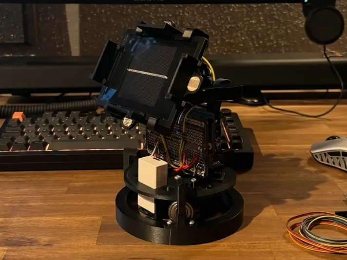

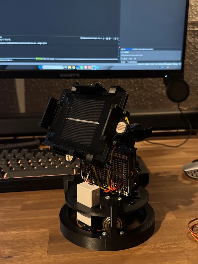
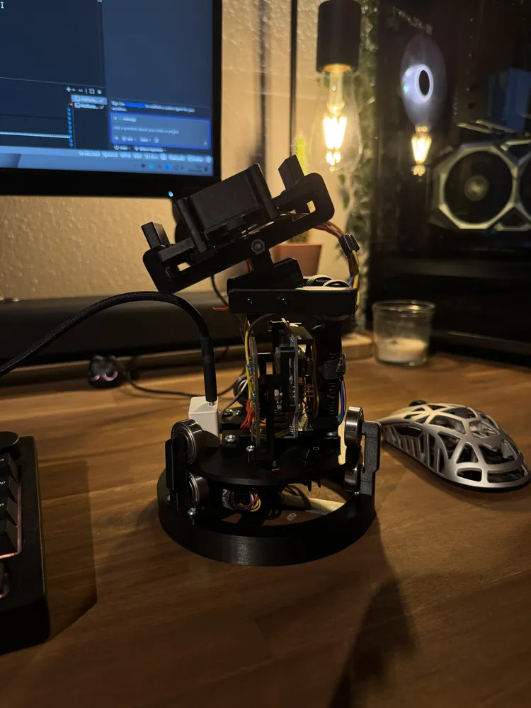
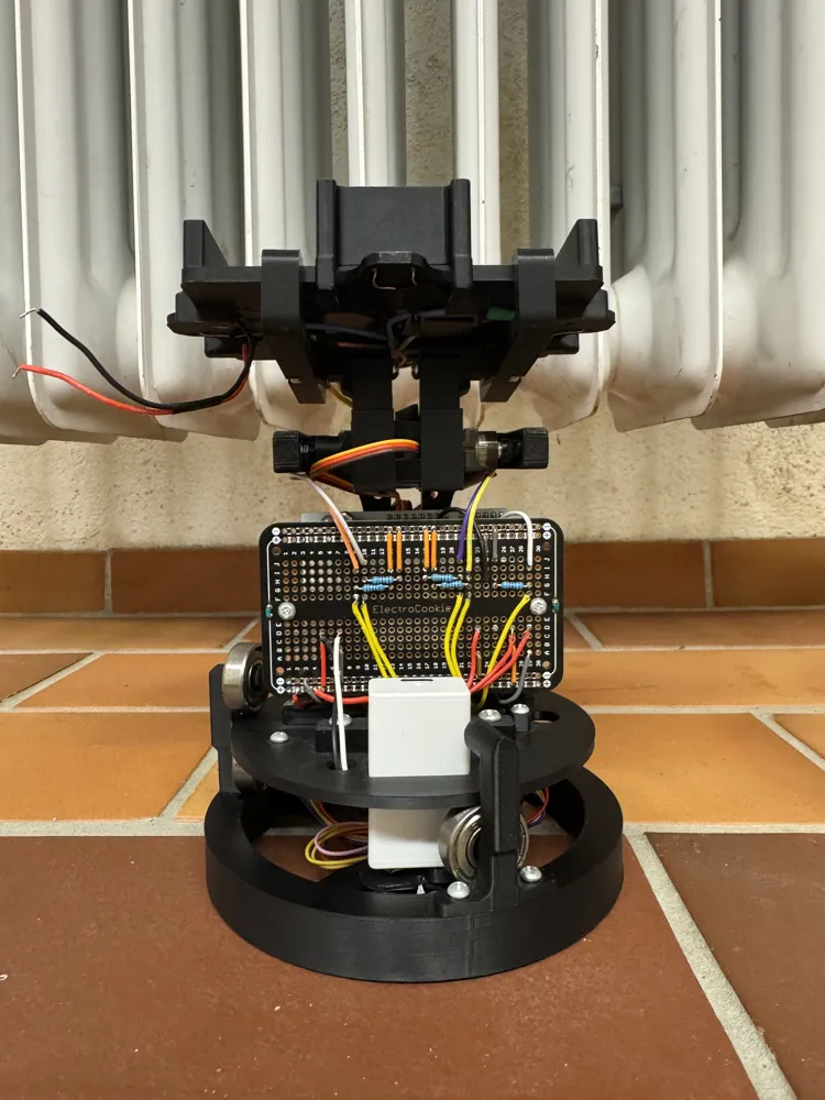
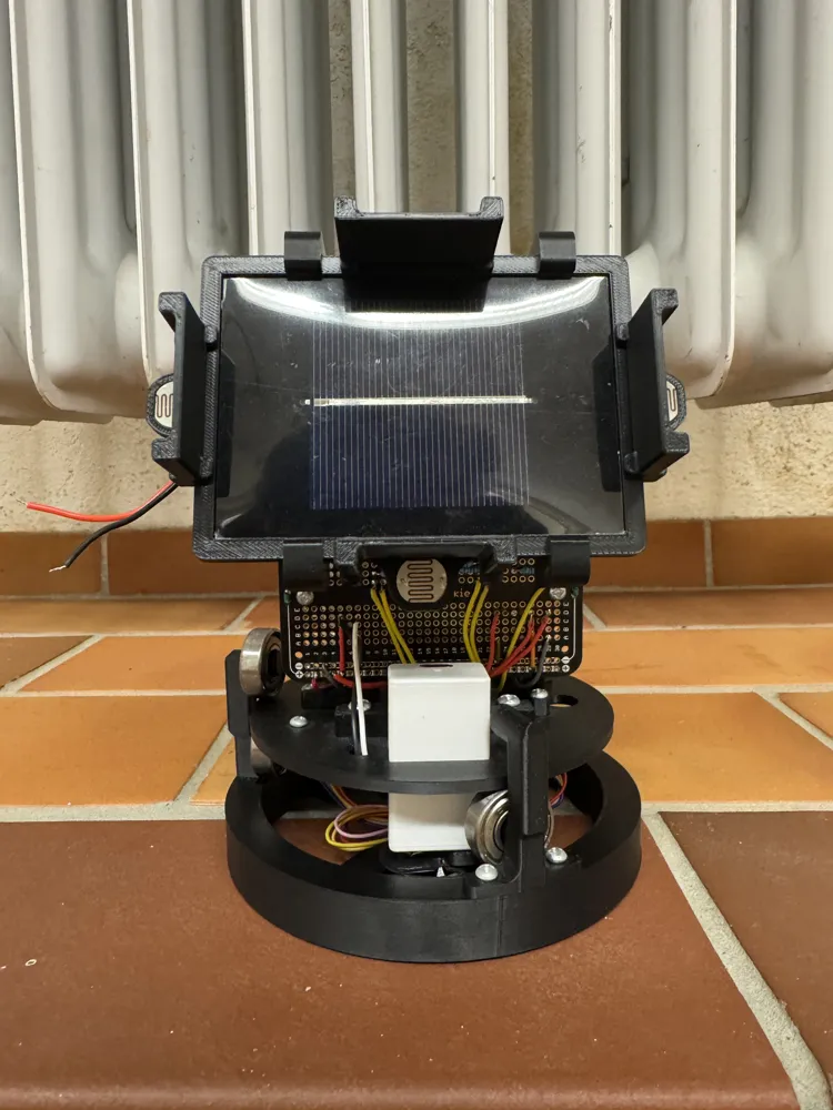
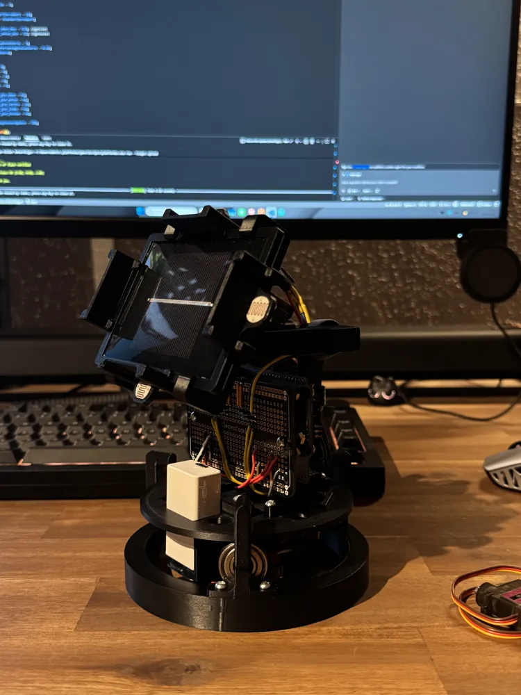
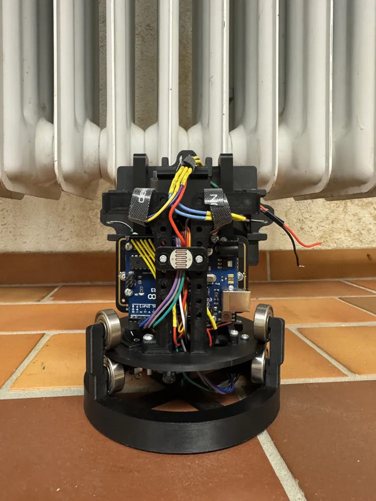
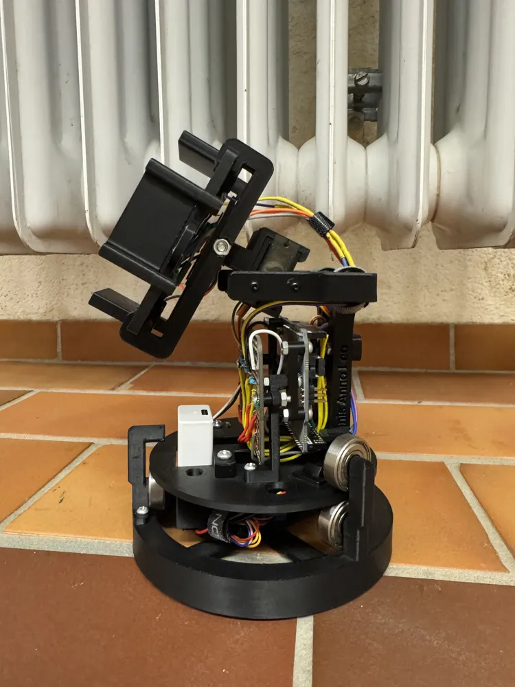
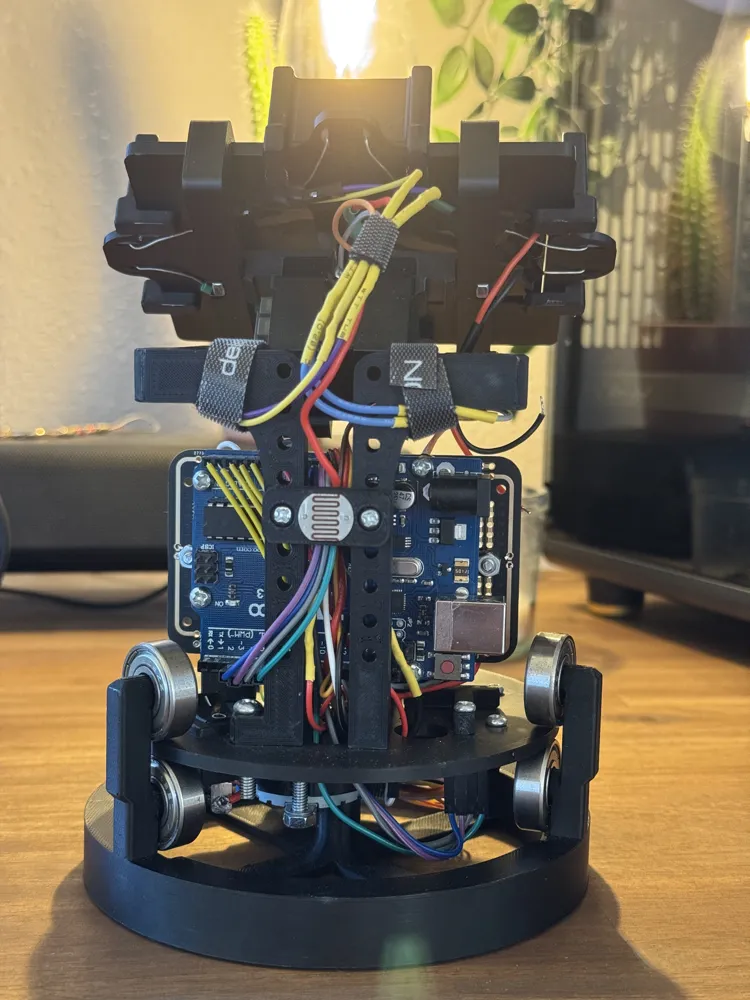
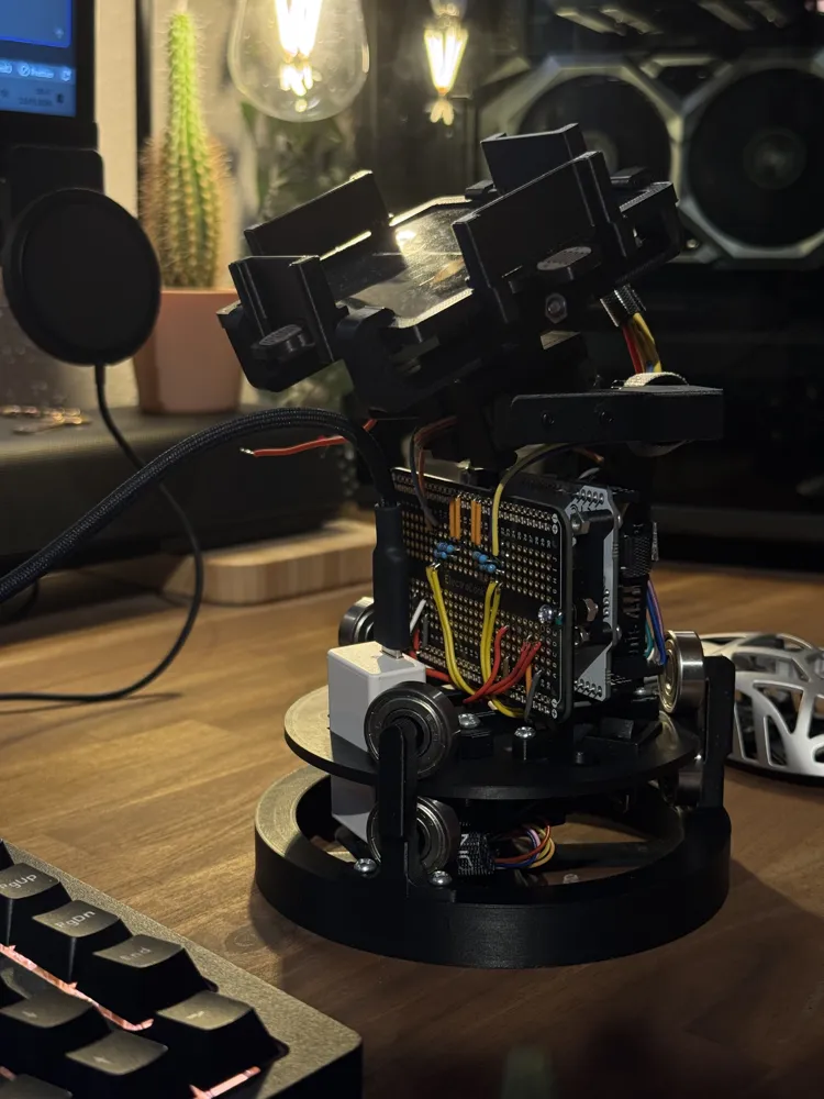
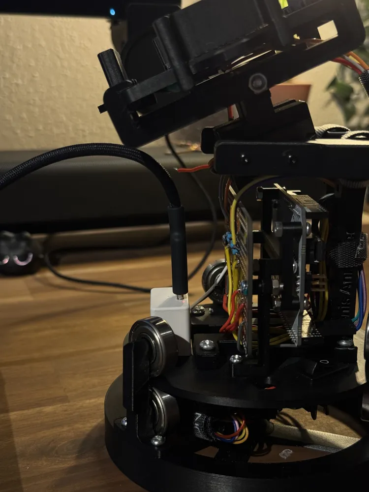
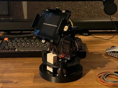
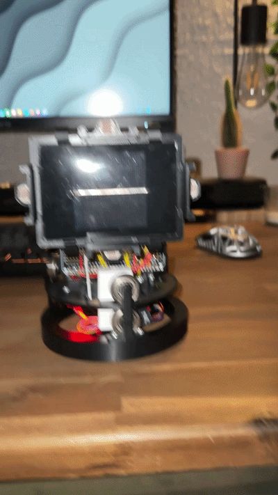
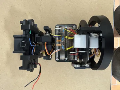
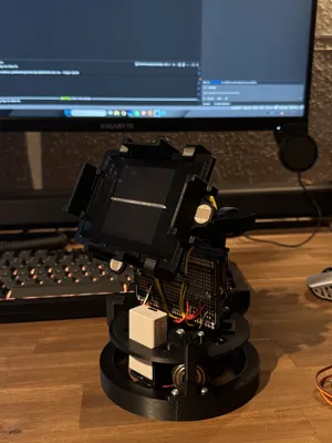
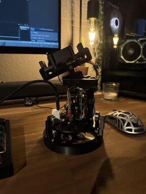
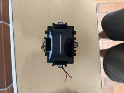
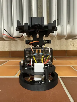
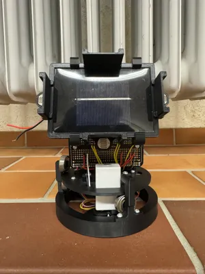
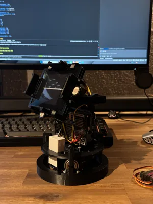
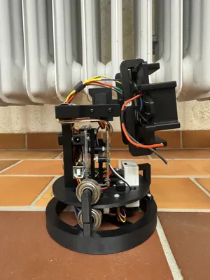
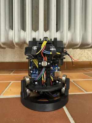
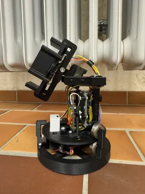
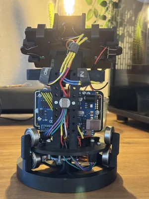
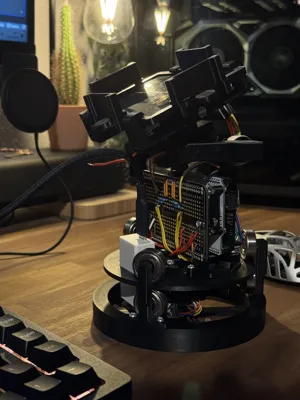
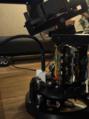
3D-printed solar tracker that automatically directs a solar panel towards the brightest light source using an Arduino, 5 LDR light sensors, and a servo and stepper motor. Developed as an NWT school project
HOW IT WORKS
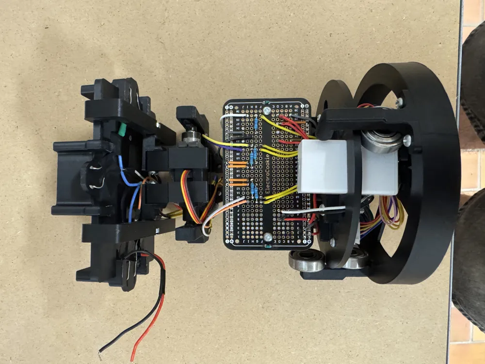
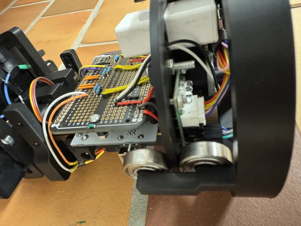
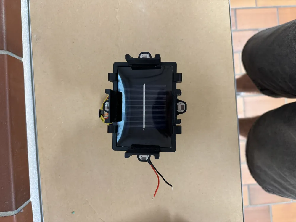
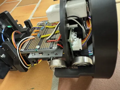
Five LDR light sensors (top, bottom, left, right, rear) are mounted using shielding 3D-printed clips so that each only detects light from its own direction. An Arduino continuously compares the sensor values and controls two motors:
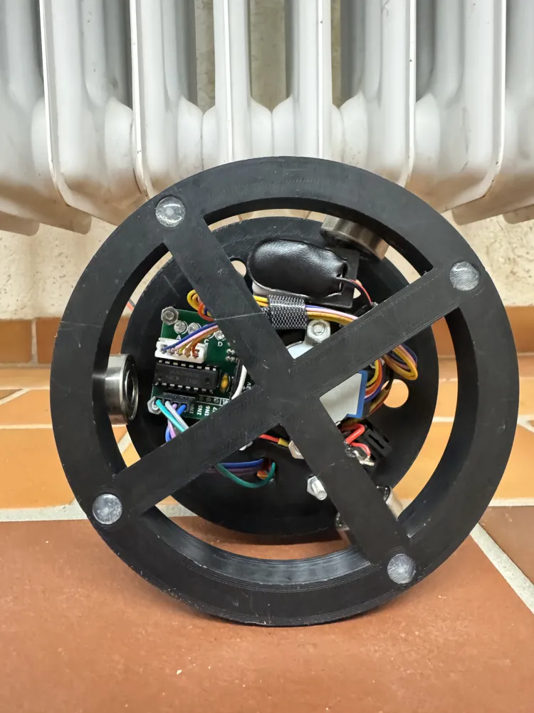
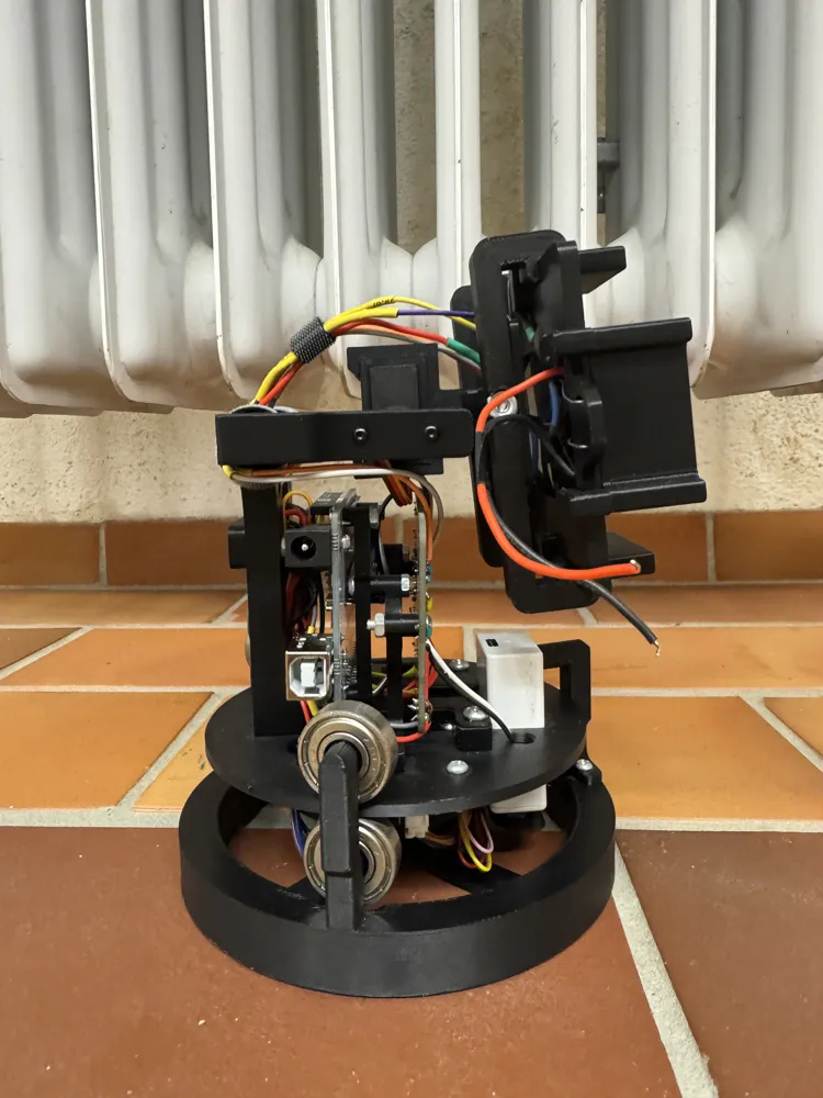
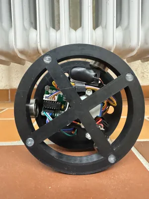
– a stepper motor that rotates the entire construction horizontally using three ball bearings
– a servo motor that tilts the solar panel vertically
A second, mechanically identical "dummy" servo serves only for stability without being controlled itself, which saves energy compared to two active servos.
To prevent the solar tracker from moving with every minimal light fluctuation, we programmed a dynamic dead zone, which we determined through our own test series. A fifth LDR on the back also detects when the light source suddenly moves behind the panel and automatically triggers a 180° rotation
-No rotation limit. Since the battery and Arduino are on the entire construction, the device can rotate as often as it wants without getting tangled
MATERIALS REQUIRED (not 3D printed)
– Arduino (Uno or compatible)
– 1× servo motor + 1× identical servo as mechanical dummy
– 1× stepper motor (28BYJ-48 with ULN2003 driver)
– 6x ball bearings (608ZZ)
– 5x resistors for the LDRs
– 1x Solderboard (Mine is from Electro cookie)
– 5× LDR photoresistors (size can be checked in the Fusion file)
– small solar cell (ours was 97mm x 66.4mm. Also adjustable in Fusion)
– (rechargeable) 9V battery + cable connector
– Screws (M3, M4, M"" in various lengths), M3/M4/M2 nuts
– Cables (standard Arduino cables)
COMPONENTS
| Component | Quantity | Note |
|---|---|---|
| Circle | 1 | Base ring Ø125 mm, supports the ball bearings |
| Support | 1 | screws onto "Circle" |
| Platform | 1 | rotatable platform Ø109 mm |
| Mount | X | Arduino/electronics mount |
| Arm_L | 1 | left arm, height 88 mm |
| Arm_R | 1 | right arm, almost identical to Arm_L (mirrored) |
| Servo Mount (3 parts) | 2× per part | one set each for servo & dummy servo (mirrored) |
| Solar Frame | 1 | Frame for the solar panel, 107 × 76.4 mm |
| Clips | 4 | LDR shielding clips, "4 identical in total" |
FURTHER INFORMATION
You probably won't have all parts with the exact same dimensions as mine — I received my components (servo, motor, Arduino) from my teacher. If your components have different dimensions, you can adjust the Fusion file accordingly via the parameters. However, the parameters are in German and some are named a bit unclearly, so it might take some time to find your way around. Overall, the Fusion file's naming is rather cluttered, but I tried my best
SPONTANEOUS ASSEMBLY NOTES
I had to drill through and enlarge the holes in the servo head (the plastic part / the servo horn) so that an M2 screw would fit through
Documentation (5)
License



Comment & Rating (0)