
Spherical Gear - Educational Model
Print Profile(1)
Description
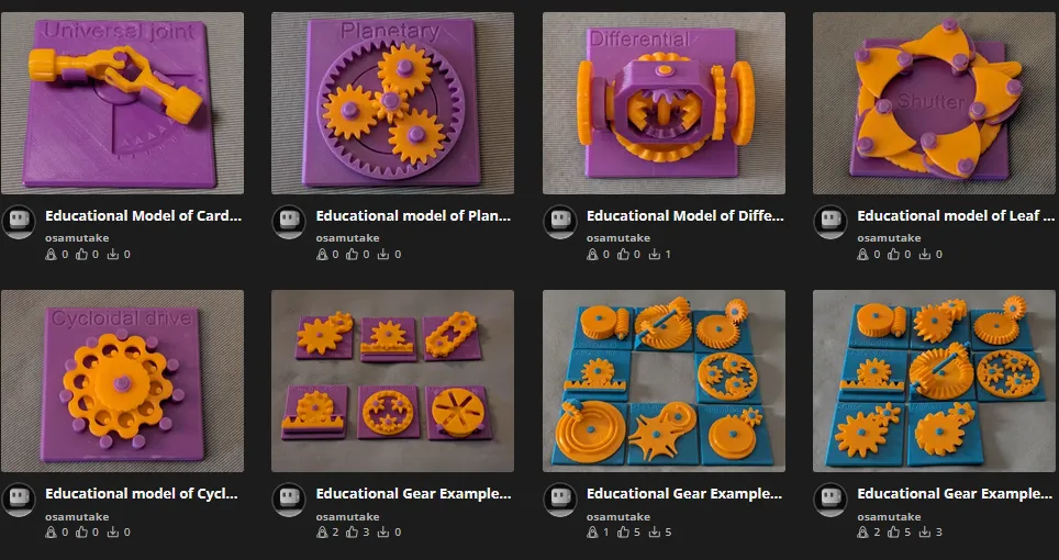
My Educational Mechanical Examples Series
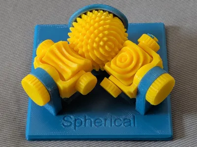
This model is one of my educational mechanical mechanism examples on 80mm x 80mm base plates.
You can find all models of the series in this collection => [Mechanical Mechanism Examples]
The present model
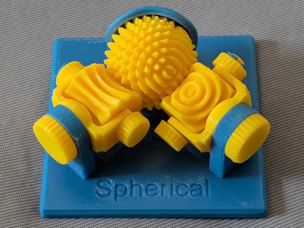
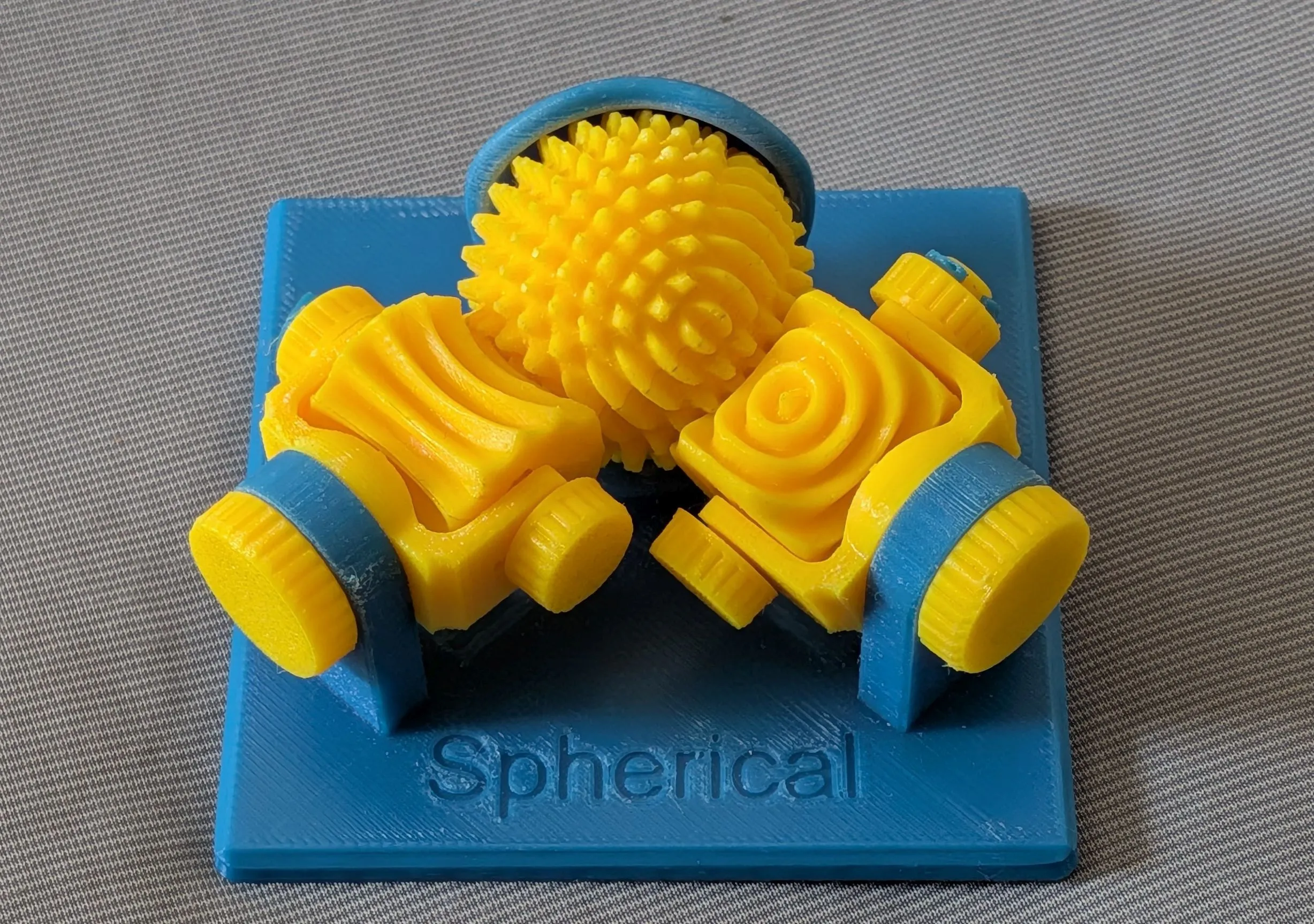
This is an educational model of a spherical gear system, which is also called as ABENICS named after the inventor's name Abe.
Brief Description


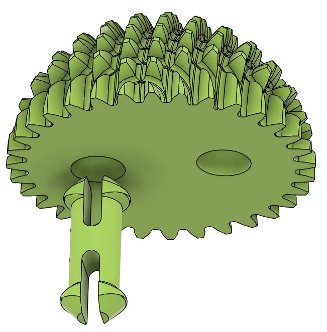
A spherical gear system consists of one spherical gear and two cylindrical gears. Each cylindrical gear can rotate around its central axis, and that axis itself can swing around a second axis pointing toward the center of the sphere. By driving these two axes independently for each cylindrical gear — four axes in total — the system can control the orientation of the spherical gear across the full range of pitch, roll, and yaw. In a real application, the only limits on the motion range come from mechanical interference between the output coupler on the sphere and the surrounding structure, not from the gear geometry itself.

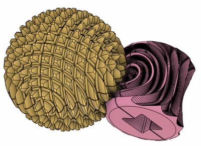

The spherical gear is constructed by engraving a spur gear tooth profile around one axis of a sphere, then repeating the process around a perpendicular axis. The gif animation below illustrates this two-step process: first one rotation, then a second rotation about an axis 90 degrees away, yielding the characteristic cross-hatched spherical surface.

The cylindrical gear is designed by rolling a basic spherical gear — engraved around only one axis — against a cylindrical blank. This process leaves one distinctive eye-shaped feature on the cylinder surface. Because of this, the cylindrical gear is also called a monopole gear.

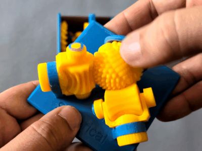
When you handle the printed model, you may notice that the spherical gear tends to stall at certain orientations. This happens when the monopole of the cylindrical gear aligns with a pole of the spherical gear. At this position, the spherical gear can not rotate in the direction of the cylindrical gear's central axis. To rotate the sphere in any intended direction, the secondary axis of the cylindrical gear must first be driven to make the main axis perpendicular to that direction. Only when the control software does this intelligently, the spherical gear can achieve motion in any arbitrary direction.
To convince yourself that the spherical gear can indeed be moved in any direction from any orientation, try the following when it locks up: put your finger on the sphere and move it in small circles. Since the lock only resists one specific rotation at a time, pushing in various directions will gradually swing the cylindrical gear into an orientation where it can drive the sphere the way you want. Try this at different orientations of the sphere and you will find that free motion in any direction is always recoverable.
The spherical gear system is a relatively new concept, first published in 2021, and is intended for robotic joints that achieve the same three rotational degrees of freedom as human joints.
Reference
- Kazuki Abe; Kenjiro Tadakuma; Riichiro Tadakuma (October 2021). "ABENICS: Active Ball Joint Mechanism With Three-DoF Based on Spherical Gear Meshings". IEEE Transactions on Robotics. 37 (5).
Case
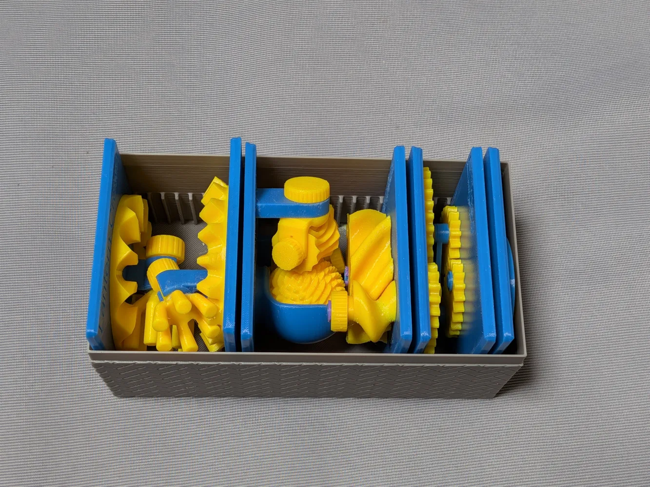
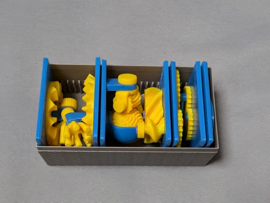
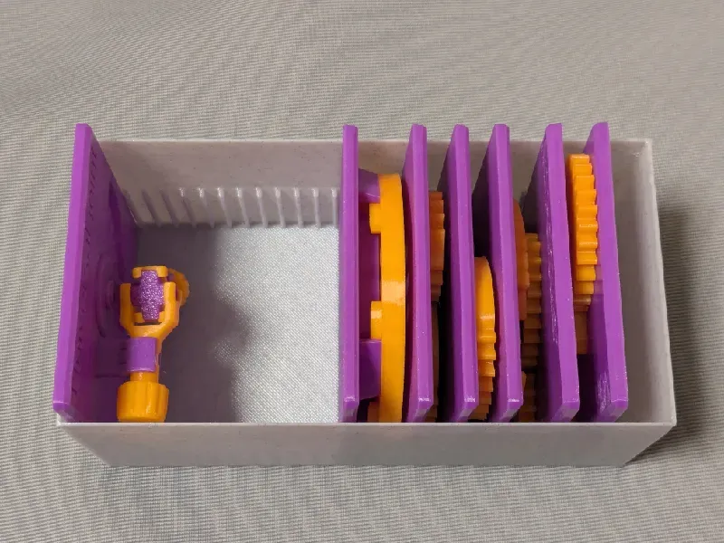
This model is compatible with the case included in my first set.
Printing
- Use the models named ???-printable.stl for printing.
The models named ???-assembled.stl are provided just to show how they should be assembled.
- Use well-dried PETG to have better dimensional accuracy.
- Use 0.1 mm or 0.08 mm layer height to have smoother surfaces.
- Use slow printing speed for overhangs.
- Select “Random” seam position to have smoother rotation.
Randomly distributed seam should be easily worn out after some wearing.Printing
Sanding and Filing
Note that, in this model, the rotation of the bases for bearings is intentionally made not too smooth.
Sometimes, the gears suffer from the stringing effect and/or elephant foot effect, resulting in a too tight fit to the shafts (they are designed with a 0.15 mm radial clearance).
If you see rough surface on the shafts due to stringing, sand off the roughness with a small piece of sand paper.
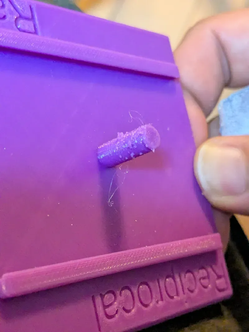
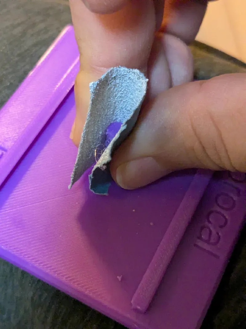
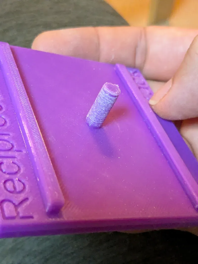
If you feel the gears do not rotate smoothly due to an elephant effect, widen the hole slightly by using a thin round bar file.
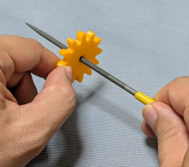
Without those issues, the parts should rotate very smoothly with minimal friction.
Assembly
(1) The spherical gear is printed in two pieces to have easy and precision printing. Combine them with two dedicated pins.
(2) The cylindrical gear is also printed in two pieces. Combine them with two dedicated pins.
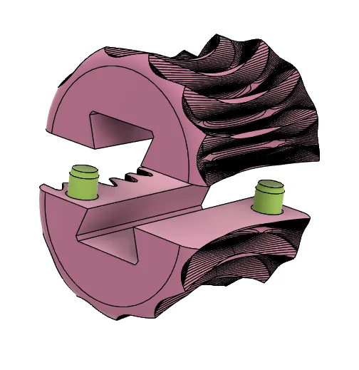
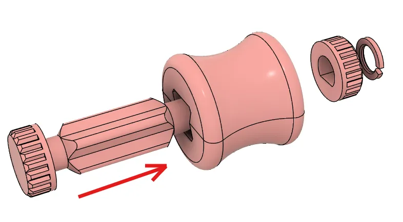
(3) Push the shaft into the cylindrical gear and secure the other knob with the retaining ring.
(The gears are simplified in these pictures to make it easy to handle in the CAD.)
(4) Mount the assembled cylindrical gear with shaft onto the bearing.
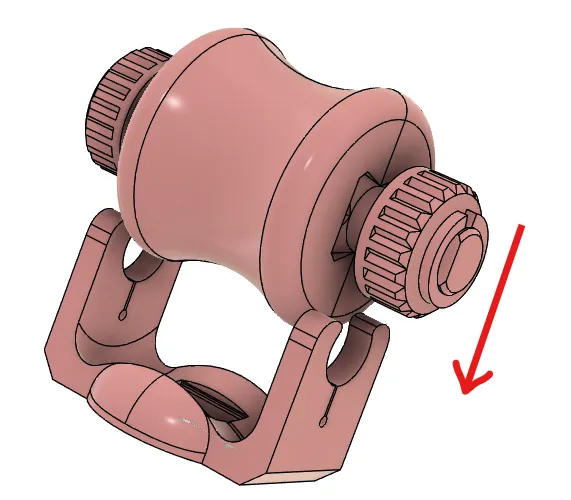
(5) Put the sphere on the plate.
(6) Put the cylindrical gear on the bearing.
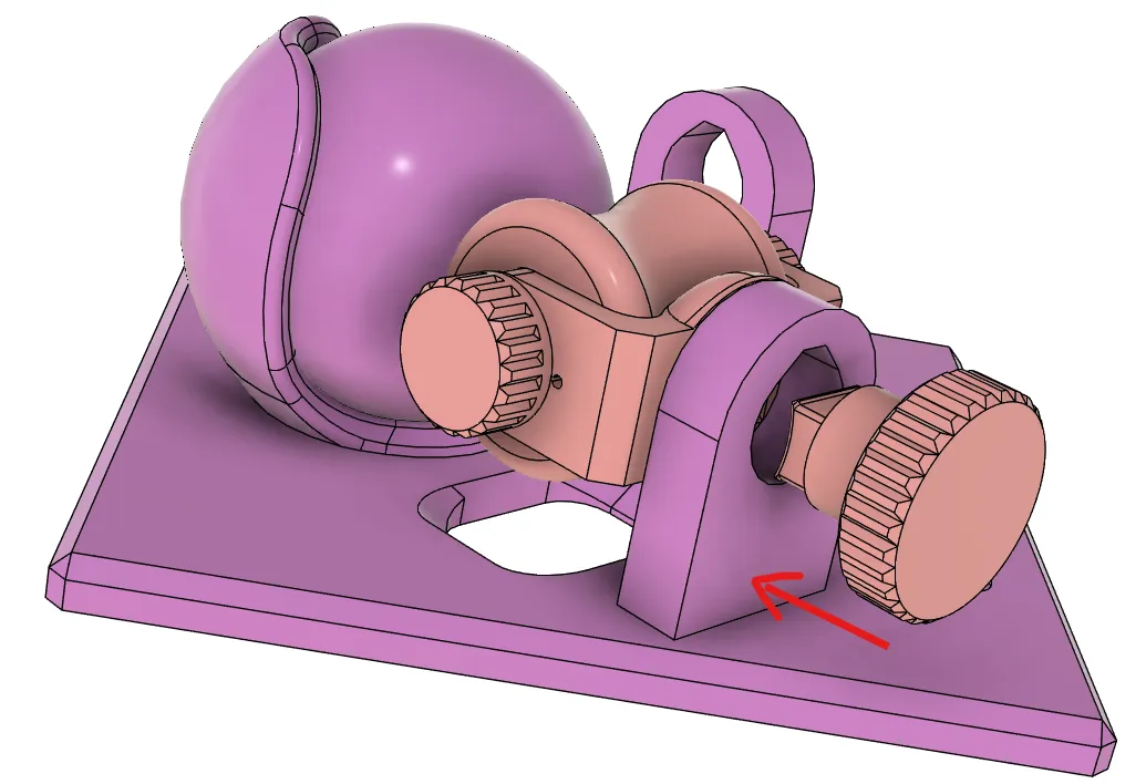
(7) Push the secondary shaft of the cylindrical gear into the bearing on the plate.
It should snap fixed in the square hole on the bottom plate of the smaller bearing.
Other examples
You may also be interested in the models in my educational mechanical mechanism examples.
Find them in this collection:
https://makerworld.com/collections/15048577-my-educational-mechanism-models
Happy printing!
Acknowledgement
I got into gears thanks to K.$uzuki's amazing articles and YouTube videos. Many of the mechanisms shown in this series came from the introductions on his website. He also makes excellent gear models himself. This series wouldn’t have existed without his inspiration.
I learned a lot about technical detail of designing gear tooth profiles from Haguruma-No-Hanashi website. I’m truly grateful for that.
License
- The 3D model(s) are licensed under Creative Commons Attribution 4.0 International.
- However, the text and images on this page are copyright reserved.
License



Comment & Rating (3)