
Capsule Vending Machine
Print Profile(1)
Description
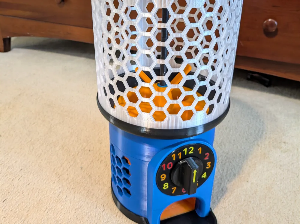
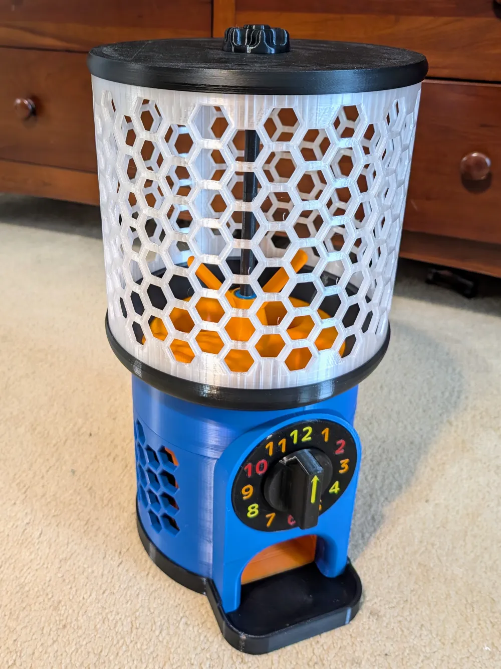
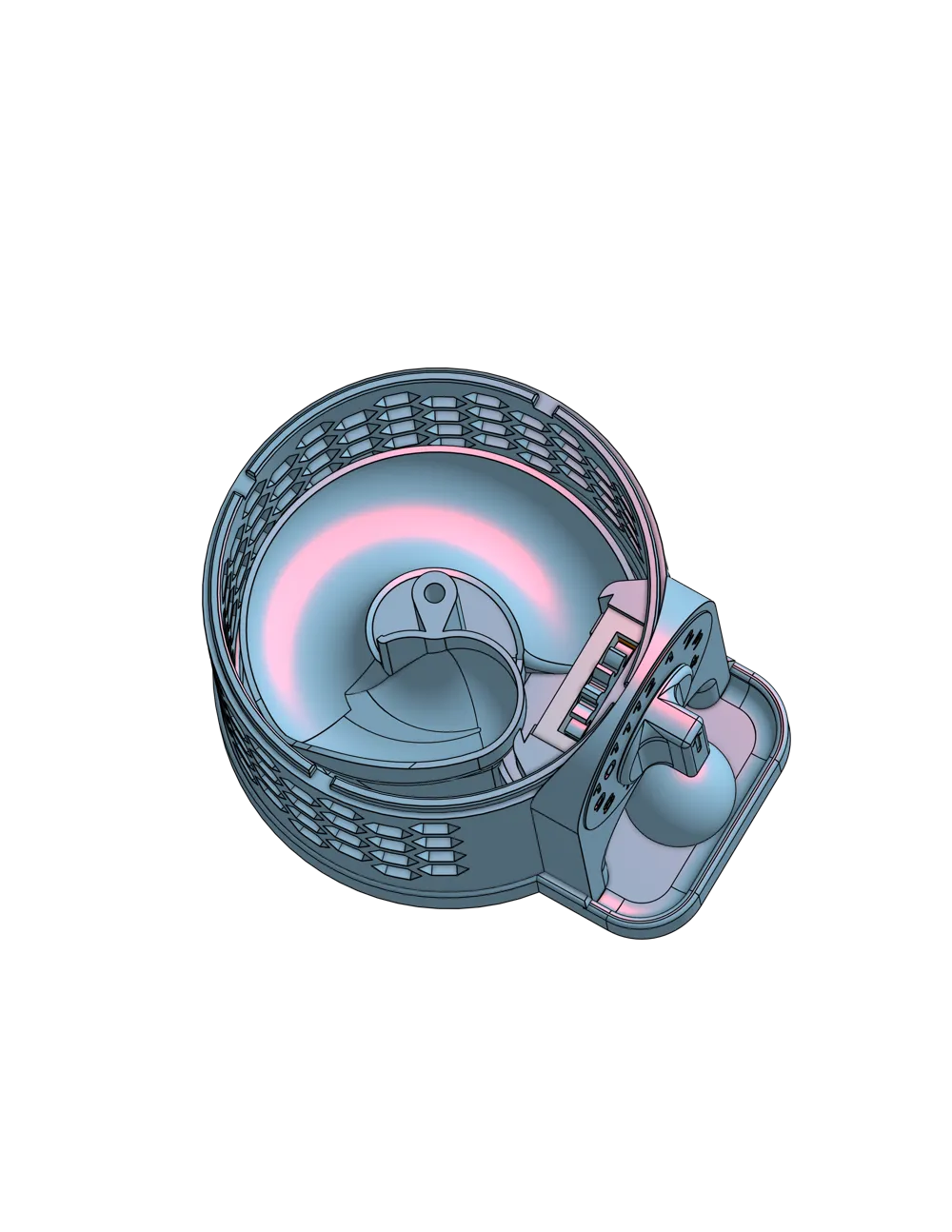
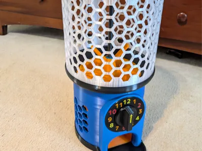
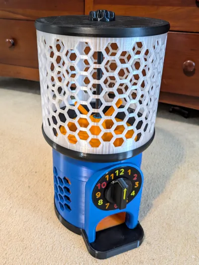
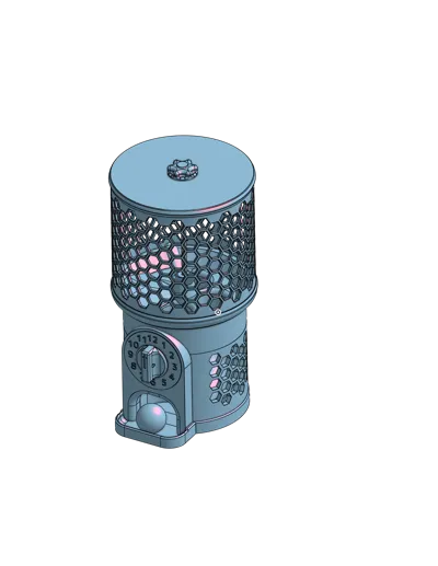
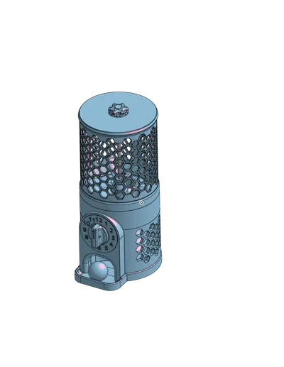
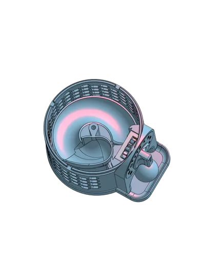
This is a fun toy capsule vending machine for classrooms, parties, playrooms, etc. It is designed to work with 2-inch (50mm) plastic capsules. Fill the capsules with toys, candy, messages, clues, fortunes, etc. A single crank yields a single, random capsule. No coins required!
Points of Interest
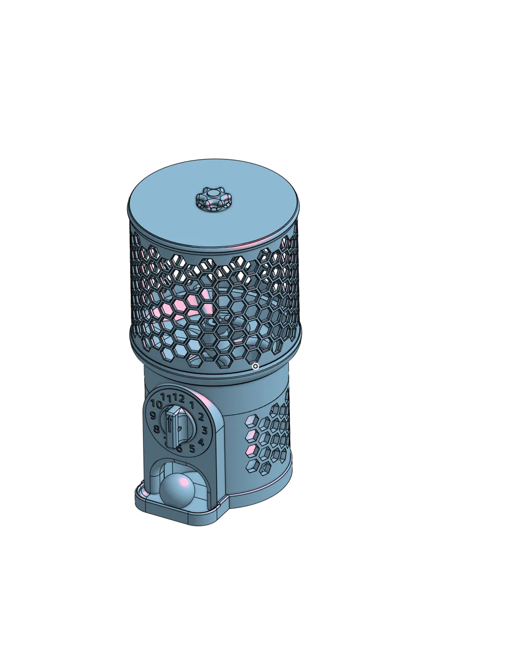
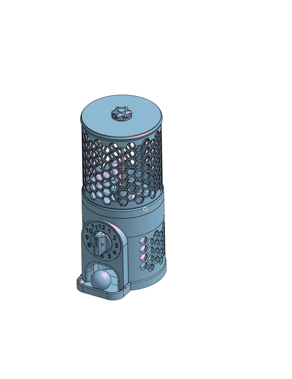
- Two bin sizes (both hold dozens of balls
- “Standard” maintains a uniform, more slim profile from bottom to top
- “Big Bin” maximizes the volume and evokes a more traditional vending machine aesthetic
- Ratcheting crank handle mimics operational sound and feel of a traditional vending machine
- Highly modular design allows countless creative color combinations, even for single-color printers
- Robust design should last for years of intended use
- Easy, glue-free assembly also allows for easy repairs should any part eventually fail
- Minimal non-printed bill of materials
Required Materials
- 2-inch/50mm Capsules
For example https://www.amazon.com/dp/B0CNJXH9DV - One M8 x 400mm Fully Threaded Rod (standard 1.25mm thread pitch)
For example https://www.amazon.com/dp/B0D3TJTYY7 - One standard M8 Hex Nut (standard 1.25mm thread pitch--NOT LOCK NUT)
For example https://www.amazon.com/dp/B0DRF8KCB7 - Four common 608-2RS Roller Skate Bearings
For example https://www.amazon.com/dp/B09PKD8QZZ - One M3 x 6mm Machine Screw (for securing the handle to the crank)
Really anything from 5-8mm is fine
#4 or #5 x ¼" is likely also fine
Required Tools
- Driver for M3 screw
- Small hammer or mallet (optional for gear assembly)
- Adjustable wrench (optional for threaded rod insertion)
Required Prints
Most of these (except for the gears) come configured for PLA, as this will introduce the least issues with potential warping on the large, round parts. However, if you're experienced and comfortable with it, PETG is the superior choice for durability and impact resistance. I do not recommend PLA for the gear asssembly (especially the stem/shaft) as it tends to be too stiff and brittle to handle the repeated torque.
Be aware, this is a large print. Expect to use around 2.2-2.5 kg of filament over a total of around 3 days of printing.
- Choose:
- EITHER Standard Bin:
- Plate 1: Standard Cap
- Plate 2: Standard Bin
- Plate 3: Standard Upper Base
- OR Big Bin:
- Plate 5: Big Cap
- Plate 6: Big Bin
- Plate 7: Big Upper Base
- EITHER Standard Bin:
- Base
- Plate 4: Mid Base
- Plate 8: Carousel (and spacers)
- Plate 9: Lower Base
This is the only one that requires supports. They are pre-painted for you, but you can tweak them if you like (e.g., use a special support material for transition) - Plate 10: Bottom
This is pre-colored for multi-color printing. The bottom and the ball chute are integrated into a single component. I do NOT recommend printing them separately as this is also the main structural component of the print. The chute ends up somewhat hidden, so if you need to, a single color is probably fine.
- Final Bits
- Plate 11: Misc (Crank and Top Nut)
This, too, is multi-color, as each number on the clock is intended to have a color distinct from the base. Likewise the handle has a colored arrow on top. I've also included blank versions of these as separate files if you want to print them blank or design your own. - Plate 12: Gears
As noted, these probably should be printed in PETG or PA or similar tough and slick material.
- Plate 11: Misc (Crank and Top Nut)
Assembly
- Insert threaded rod into printed Bottom.
The metal rod just screws into the hole in the middle of the chute. This should bottom out at the correct height. Don't overtighten (it's metal on plastic afterall), though if you need extra leverage, you can use two nuts as jam nuts (put both on the end of the rod and hand tighten them together--then tighten the rod by using a wrench to turn the top nut clockwise and loosen by turning the bottom nut counter clockwise). Assemble the gear mechanism. These should all be pretty tight, so use a small hammer or mallet if needed.
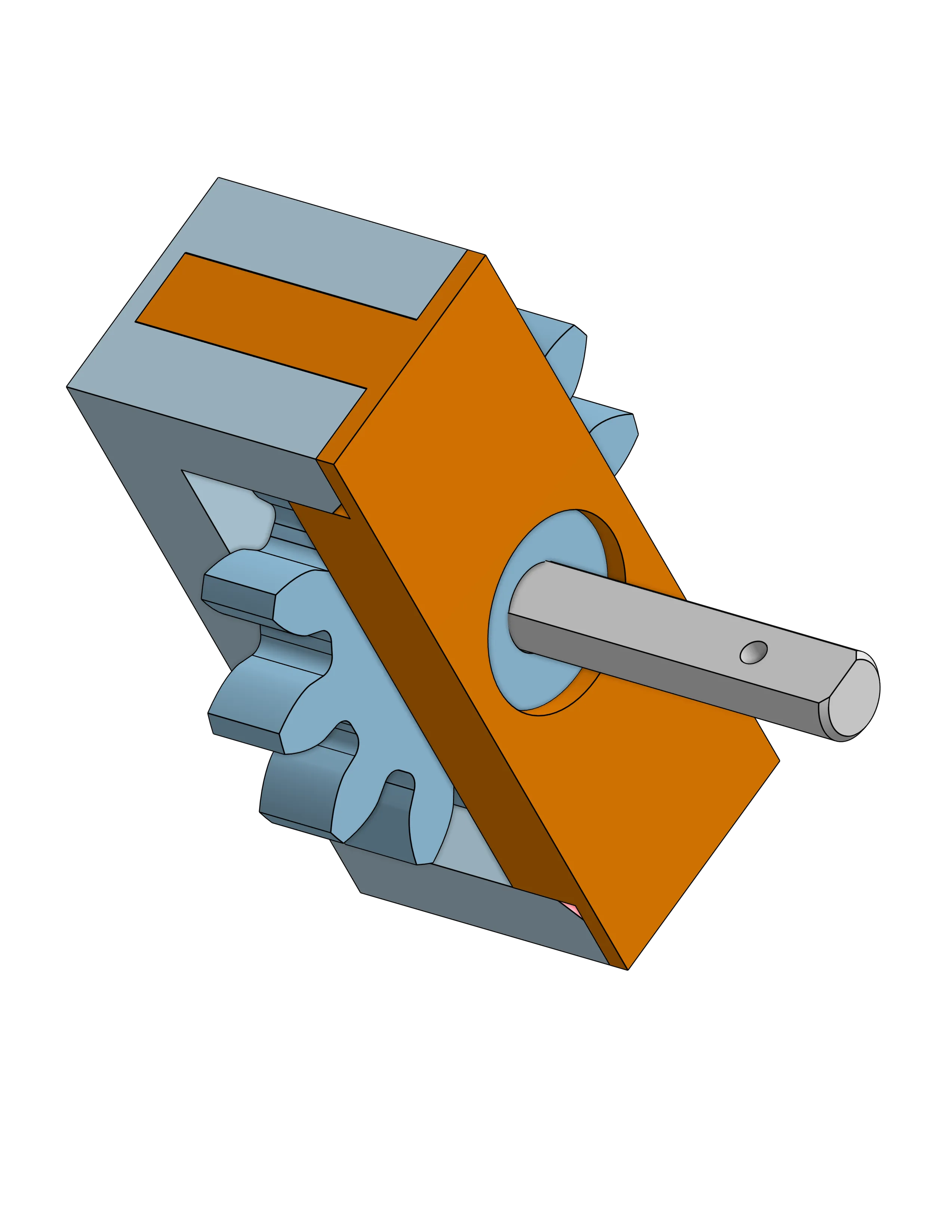
- Add bearings to the slots on both sides of the gear “Case”
- Place one side of the case on a table with the “fingers" pointing up and insert the gear into the hole in the middle of the bearing.
- Insert the gear stem into the corresponding hole in the gear. The “short” side goes into the gear and it should seat fully with the raised shoulder.
- Slide the other half of the gear case onto the gear stem and slide to engage and fully seat the fingers as shown in the figure on the right.
- Insert gear case into lower case.
- Slide gear case through the bottom so that the stem extends through the crank hole.
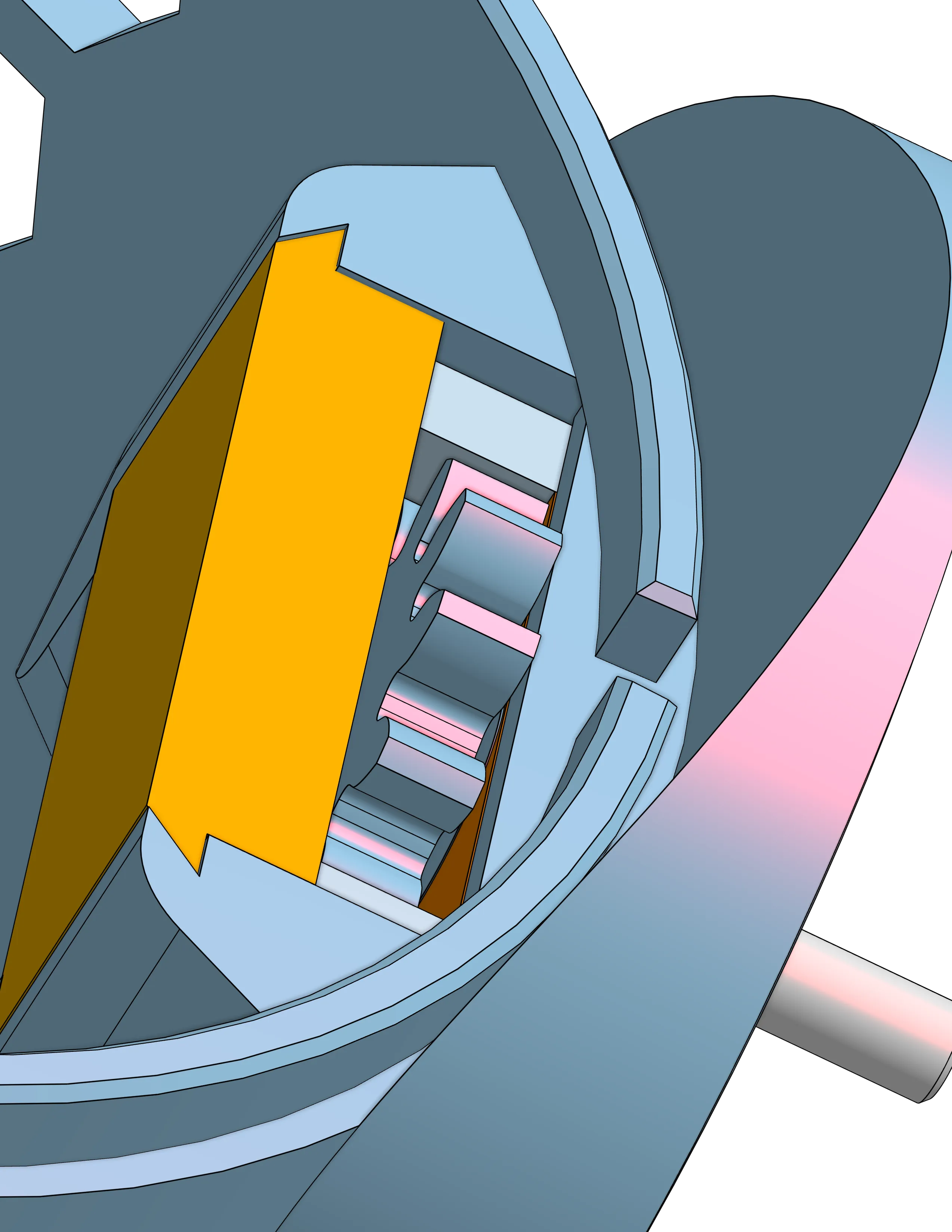
Slide the gear lock panel into the lower case to secure the gear case in place as shown in the figure on the right.
- Attach printed bottom and lower base.
The lower base should slide easily over the chute on the bottom, with the lower base's gate being aligned with the bottom's chute exit. Fully seat the lower base into the associated slots on the bottom; it should be a snug friction fit. - Add crank face and handle.
- Slide printed face onto the gear stem. This may be a tight fit so use a little force if needed, but be careful not to bend or break the stem. Fully seat the face onto the lower base; it will pass through the gear stem hole in the lower base and align vertically using two alignment nibs.
- Slide the crank handle onto the end of the gear stem.
- Secure the handle by screwing an m3 x 5mm (up to 8mm) screw into the side of the handle. It will self-tap threads into the hole in the stem.
- Turn the handle and ensure that the gear turns easily and smoothly.
- Attach mid base (carousel housing) to lower base.
Slide the printed mid base onto the threaded rod. This will be snug, but the rod should “sand” the opening enough to slide down easily from the top. Align the gear slot with the gear and fully seat the mid base into the appropriate slots in the lower base. Attach and align the carousel.
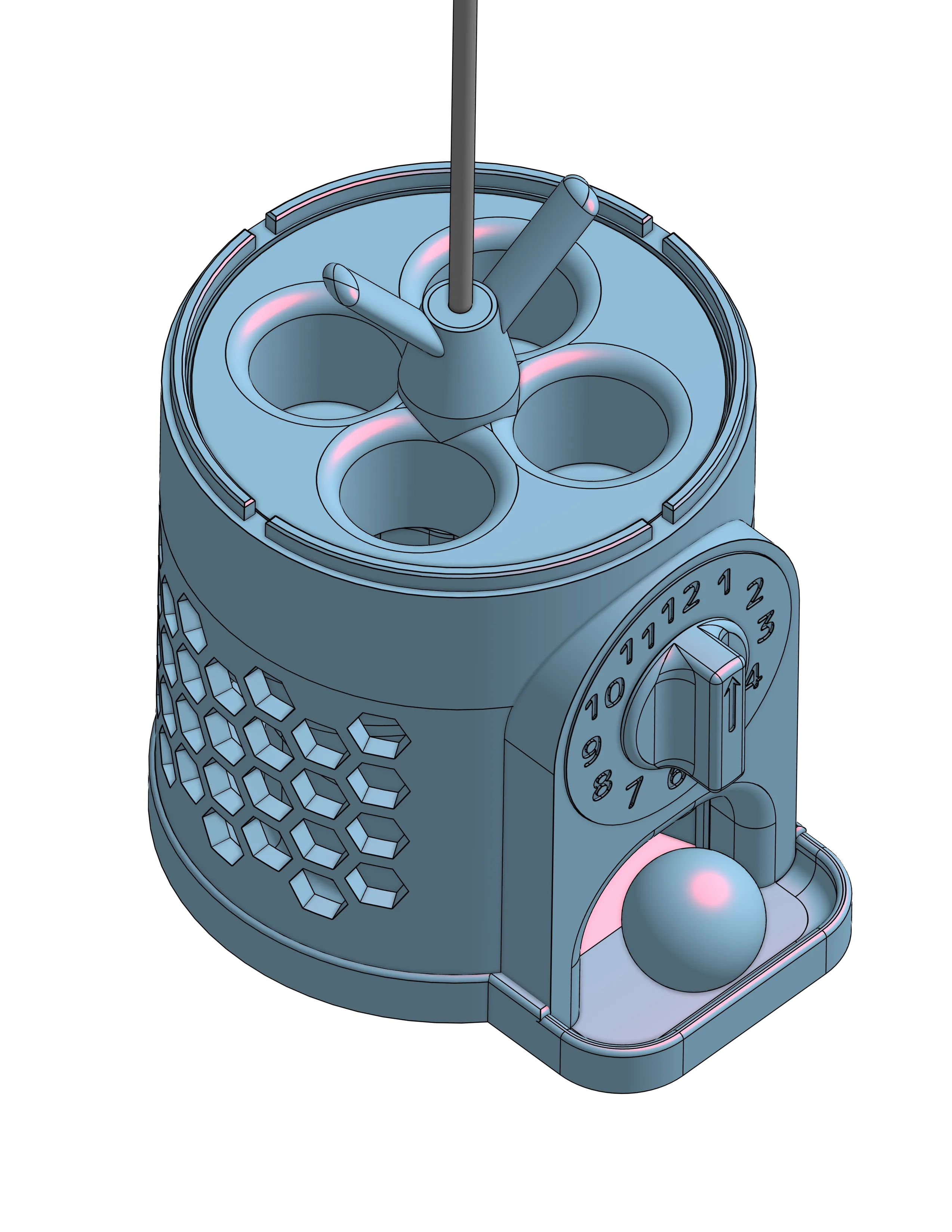
- First insert a bearing into the cutout in the middle of the bottom of the carousel.
- Slide the carousel onto the threaded rod; the rod will go through the middle of the bearing.
- Slide the smaller “inner” carousel bearing spacer onto the threaded rod and down into the cavity in the middle of the carousel.
- Slide the final bearing onto the threaded rod and seat it fully into the cutout at the top of the carousel.
At this point you will be able to lift and lower the carousel assembly onto the gear teeth. While holding the crank handle with the arrow facing up, align the carousel such that the ratchet flaps (pawls) are in the middle of one of the areas empty of any ratchet teeth. The crank should be able to spin freely from 11 to 1 before engaging with any of the ratchet teeth. This is how you know your carousel is properly aligned.
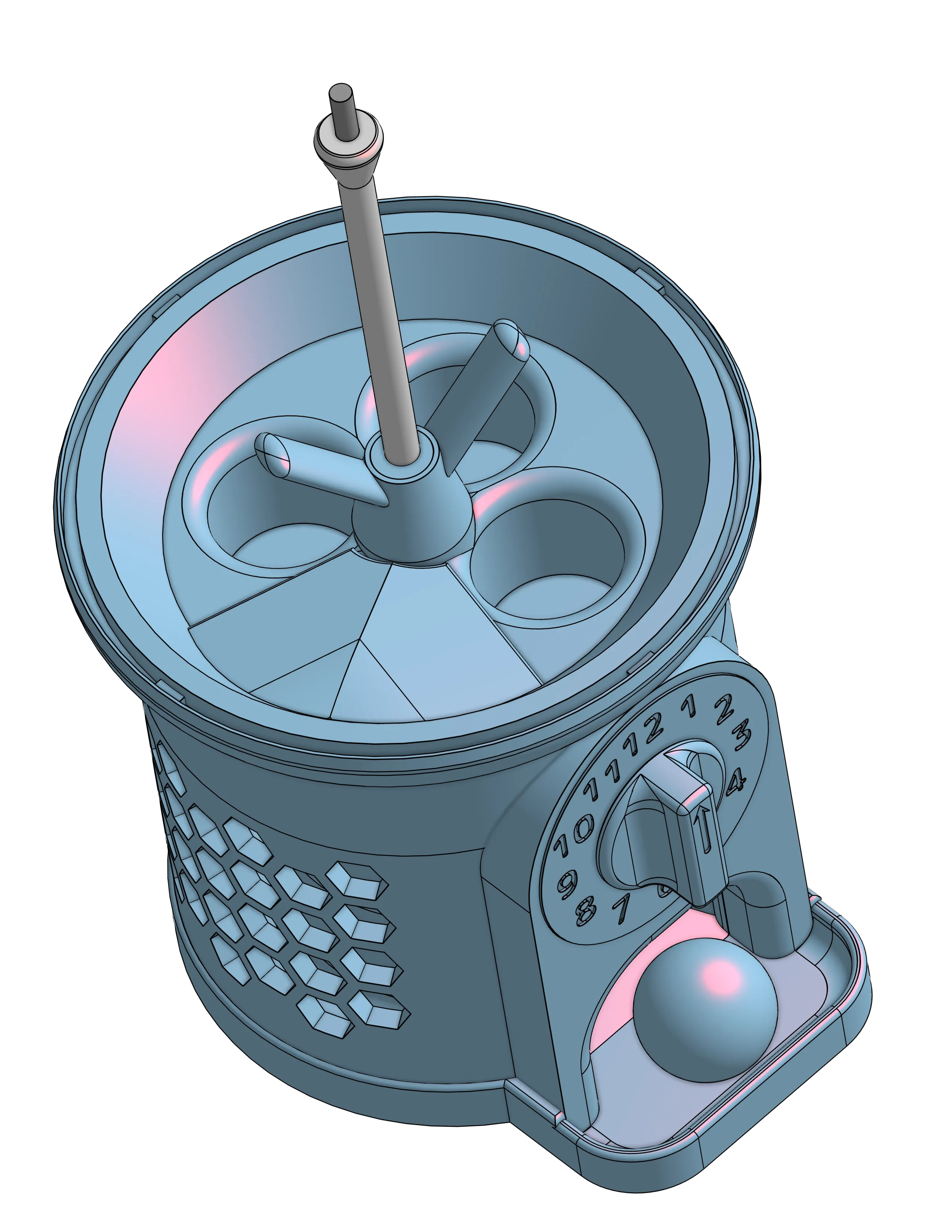
- Add the final two carousel bearing spacers to the threaded rod so that the “bulb” is at the top near the end of the threaded rod.
- Attach the upper base so that the hole cover is at the front-left of the machine, covering the chute entrance.
- Add the bin, aligning the tabs as required to seat the bin in the slots in the upper base and the part of the bin without holes is at the rear.
- Add the cap.
- Assemble and secure the top nut.
- Insert a single M8 hex nut into the slot in the top nut.
- Slide the top nut insert into the slot to lock the hex nut into place.
- Screw the top nut into place to secure the cap.
- Enjoy!!
Please let me know if you have issues or need clarification. I will update these instructions and add a FAQ section if and as needed.
License



Comment & Rating (0)