
Parametric Pipe connectors, and mounts - OpenSCAD

Print Profile(3)
Description
Boost Me (for free)
Thank You :)
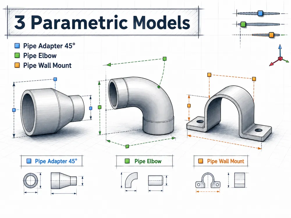
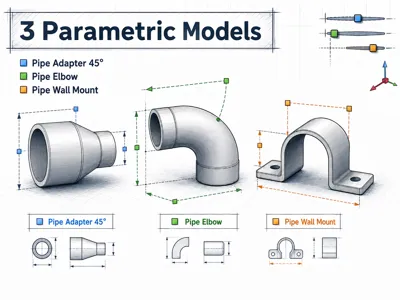
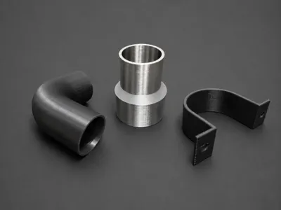
3 Parametric Pipe Models
This set includes three fully customizable pipe models for the MakerWorld Parametric Model Maker. All dimensions are specified in millimeters and can be changed directly before generating the model.
Included are:
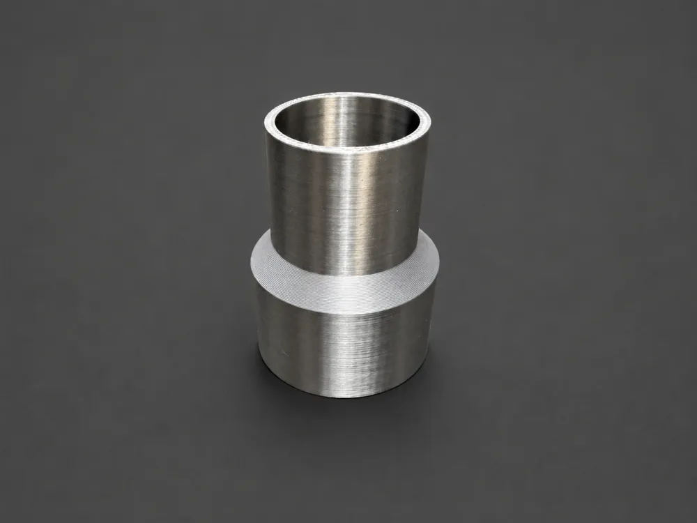
- a straight pipe adapter for increasing or reducing a diameter
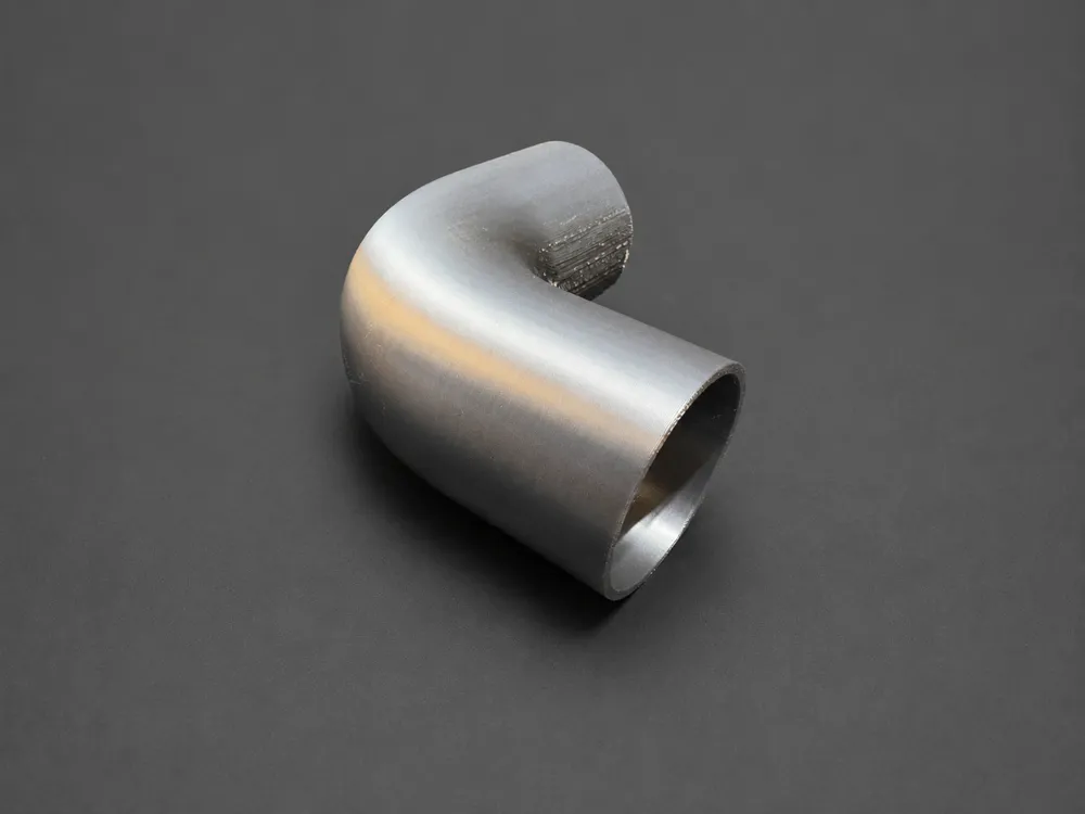
- a pipe elbow with a freely adjustable angle
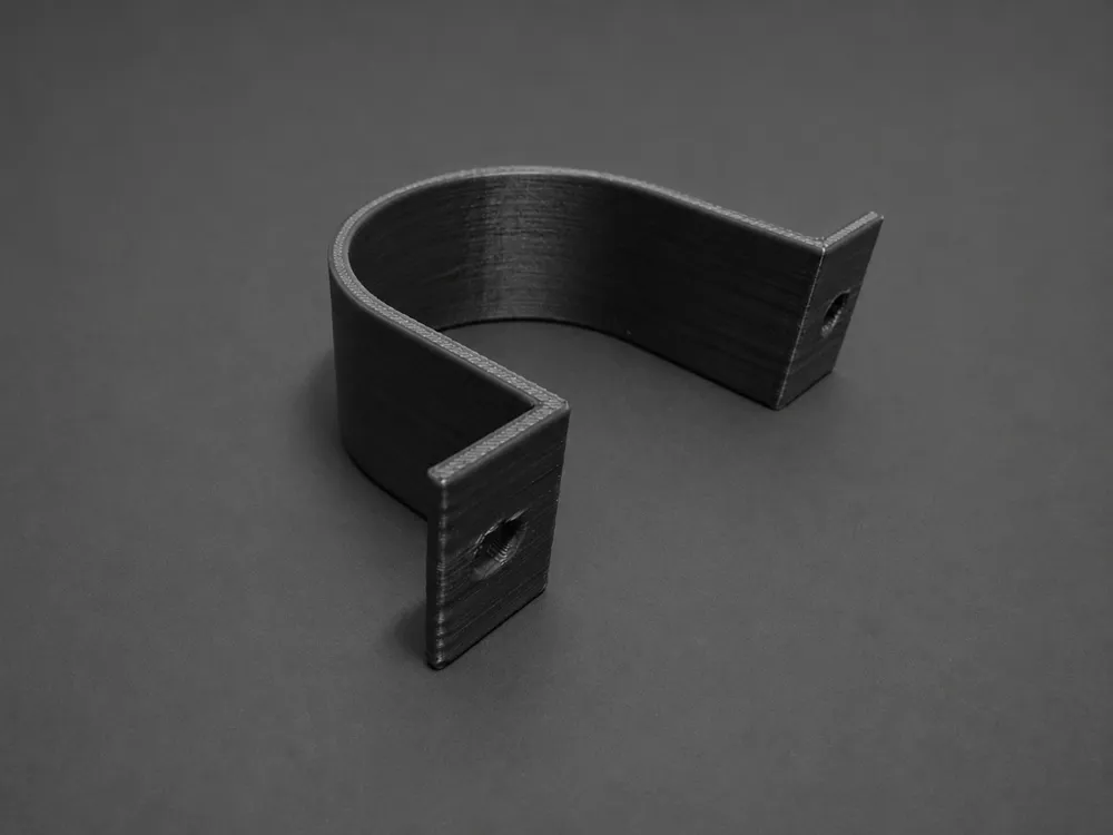
- a U-shaped pipe mount for the wall
These models are suitable for workshop projects, extraction systems, ventilation, cable routing, model making, and custom pipe installations, among other uses.
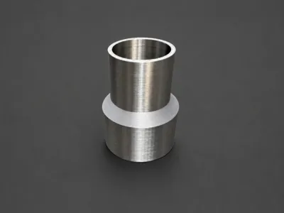
1. Pipe Adapter / Reducer with 45° Transition
The pipe adapter connects two different pipe diameters. Between the two straight pipe sections is an automatically calculated conical transition with a flank angle of 45°.
The adapter can be used as both a reducer and an enlarger. If both diameters are identical, a straight pipe section is automatically created.
Adjustable Parameters
- diameter_1 – outer diameter of the first side
- diameter_2 – outer diameter of the second side
- thickness – wall thickness of the adapter
- length – length of each straight pipe section up to the 45° transition
The length of the conical transition is automatically calculated based on the two diameters.
Important
diameter_1 and diameter_2 refer to the outer diameters of the printed adapter. The respective inner diameters are calculated as:
Inner diameter = Outer diameter − 2 × Wall thickness
The term "45°" here describes the conical transition between the diameters and not a change in the pipe's direction.
Suitable for
- pipe reductions and pipe enlargements
- extraction and ventilation ducts
- hose and device connections
- workshop adapters
- custom transition pieces
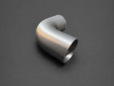
2. Parametric Pipe Elbow
The second model creates a curved, hollow pipe section with a freely adjustable change in direction. This allows for the creation of, for example, 30°, 45°, 60°, or 90° angles.
On both sides of the bend, there is a straight pipe section of identical length.
Adjustable Parameters
- diameter – outer diameter of the pipe elbow
- thickness – wall thickness of the pipe elbow
- length – straight pipe length per side, measured from the bend
- angle – desired change in direction in degrees
The bending radius is automatically generated to match the set pipe diameter.
Important
diameter refers to the outer diameter of the printed pipe elbow. The inner diameter is calculated as:
Inner diameter = diameter − 2 × thickness
The length parameter applies to both sides individually. With a setting of 30 mm, the elbow therefore has a straight pipe section of 30 mm before and after the bend.
Suitable for
- pipe systems with custom angles
- extraction and ventilation systems
- cable or hose routing
- model making
- prototypes and special solutions
3. Pipe Mount for the Wall
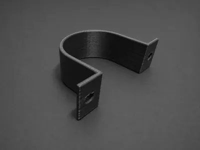
The third model is a U- or Omega-shaped pipe holder. The pipe is enclosed by the curved section, while the two outwardly folded ends can be attached to a wall or another flat surface.
Screw holes are located in the two mounting tabs.
Adjustable Parameters
- diameter – outer diameter of the pipe to be mounted
- thickness – material thickness of the mount
- width – width of the mount along the pipe
The length of the two mounting tabs is automatically adjusted to the pipe diameter.
Fit and Screw Holes
The model has a default radial clearance of approximately 0.4 mm. This makes the inner diameter of the mount about 0.8 mm larger than the set pipe diameter.
Example:
diameter = 40 mm Inner diameter of the mount ≈ 40.8 mm
The two mounting holes in the current version have a diameter of 4.5 mm, making them suitable for M4 screws, for example.
Suitable for
- mounting pipes and hoses
- cable and conduit routing
- workshop and garage installations
- extraction pipes
- light pipe systems and model making projects
The possible load depends on the filament used, wall thickness, print orientation, screws, and the respective substrate.
3D Printing Notes
PLA or PETG are suitable for normal applications. For warmer environments, workshops, or areas with higher mechanical stress, PETG, ASA, or a comparably resilient material is usually more suitable.
The following settings can be used as a starting point:
Layer height: 0.20 mm Wall loops: 4–6 Top/bottom layers: 4–6 Infill: 25–40 %
The pipe adapter can usually be printed without support material due to its 45° transition. The wall mount should be positioned flat on the print bed with its two mounting tabs. For the pipe elbow, support material may be required depending on the chosen angle and orientation.
For plug-in, clamp, or adhesive connections, a suitable printing tolerance should also be considered. This depends on the printer, filament, and desired fit. For a loose plug-in connection, a clearance of about 0.2 to 0.5 mm per side is often useful. A short test print is recommended for precise connections.
License

You shall not share, sub-license, sell, rent, host, transfer, or distribute in any way the digital or 3D printed versions of this object, nor any other derivative work of this object in its digital or physical format (including - but not limited to - remixes of this object, and hosting on other digital platforms). The objects may not be used without permission in any way whatsoever in which you charge money, or collect fees.


Comment & Rating (1)