
Universal Small Switch Stand
Print Profile(1)
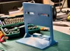
Description
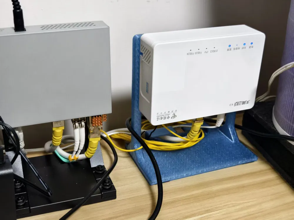
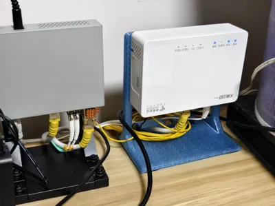
This guide applies to this universal switch desktop stand, supporting network devices with wall-mount hole spacing between 25mm - 55mm.
---
## 📦 Required Hardware Accessories
Before starting assembly, please prepare the following standard hardware components:
| Part Name | Specification | Qty | Description |
| :--- | :--- | :--- | :--- |
| **Flat Head Screw** | M4 x 14 mm | 2 | Core mounting screws |
| **Nylon Lock Nut** | M4 | 2 | Used to define and secure the mounting clip gap |
| **Standard Hex Nut** | M4 | 2 | Used for final tightening on the back of the stand |
---
## 🛠️ Detailed Assembly Steps
### Step 1: Prepare Mounting Screws and Adjust Gap
1. Take out the **M4 Flat Head Screw** and **M4 Nylon Lock Nut**, and thread the nut onto the screw.
2. **Crucial Step**: When threading, please **leave a 2 - 3 mm gap** between the screw head and the nylon lock nut (i.e., the exposed thread thickness). This gap is used for inserting into the wall-mount hole on the back of the switch.
> 💡 *Helpful Tip: Nylon lock nuts have an internal anti-loosening rubber ring, making them harder to turn. It is recommended to use a small wrench or pliers to hold the nut, then rotate the screw with a screwdriver.*
### Step 2: Attach Screws to the Switch
1. Insert the two prepared "screw + nylon lock nut" assemblies into the wall-mount installation holes on the back of the switch.
2. Pull towards the narrow opening of the slot to ensure the screw head is firmly caught in the switch's mounting hole and does not fall off.
### Step 3: Combine with Stand and Adjust Rail
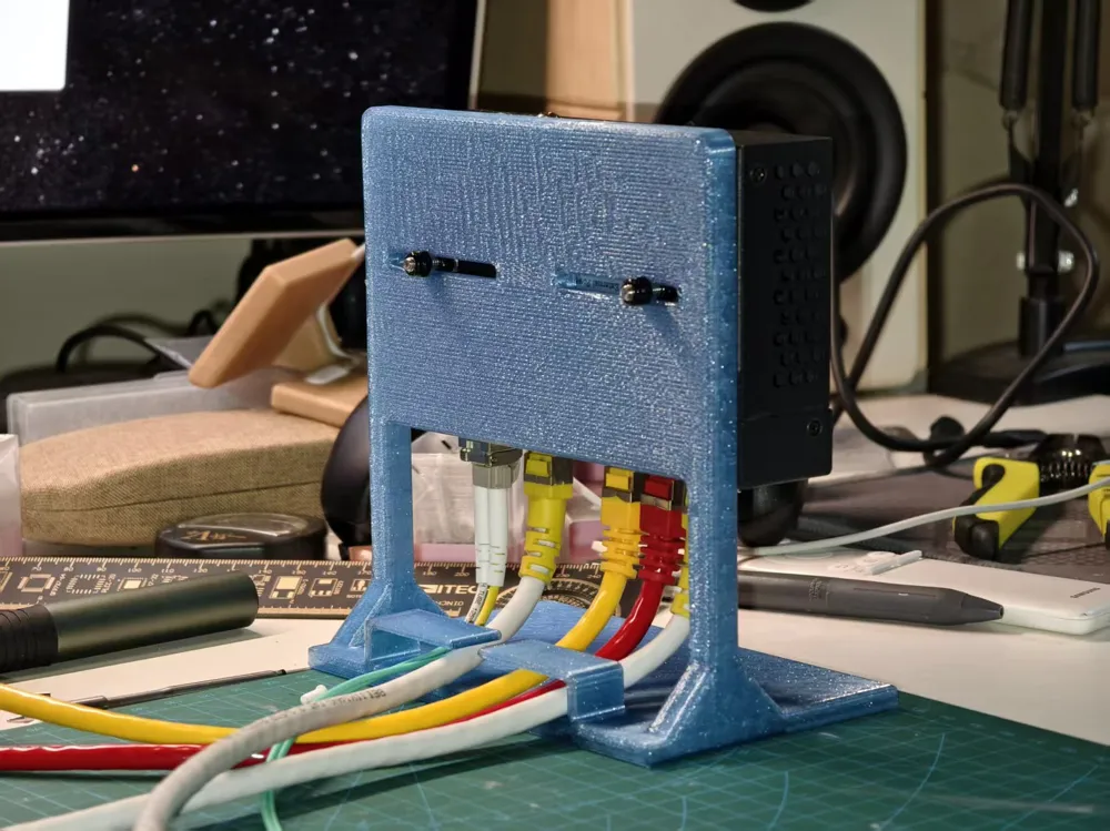
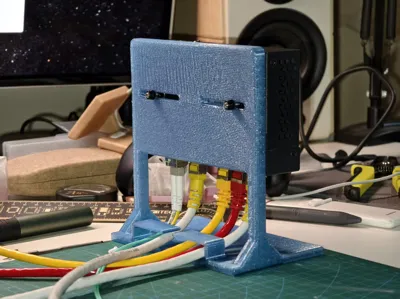
1. Guide the remaining threads exposed behind the nylon lock nut **through the two horizontal slots (rails) on the front of the stand**.
2. At this point, the switch can slide left and right on the rails. Please adjust it to the center or your desired ideal horizontal position.
### Step 4: Lock and Secure from the Back
1. Keep the front switch position fixed, and screw **M4 Standard Hex Nuts** onto the exposed threads on the **back of the stand**.
2. Use a screwdriver to tighten the hex nuts from the back, ensuring the switch is tightly clamped and fixed on the stand, preventing any wobbling.
---
## 💡 Cable Management & Design Details
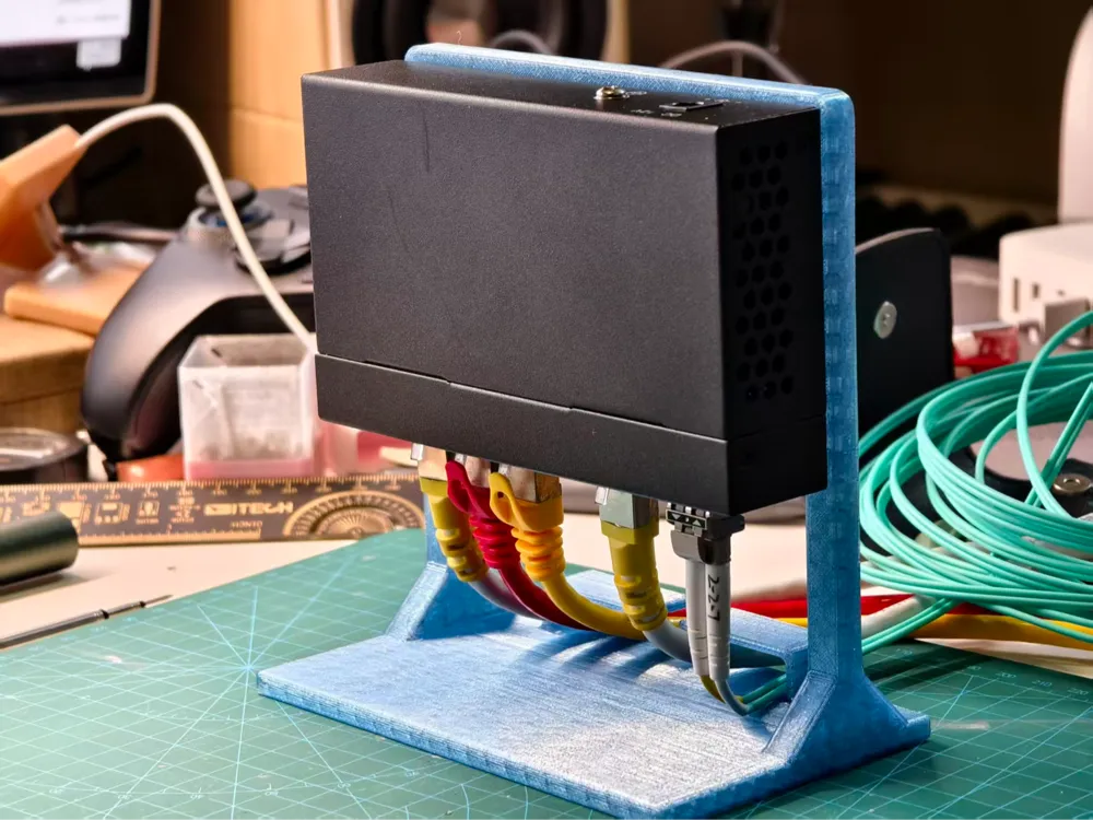
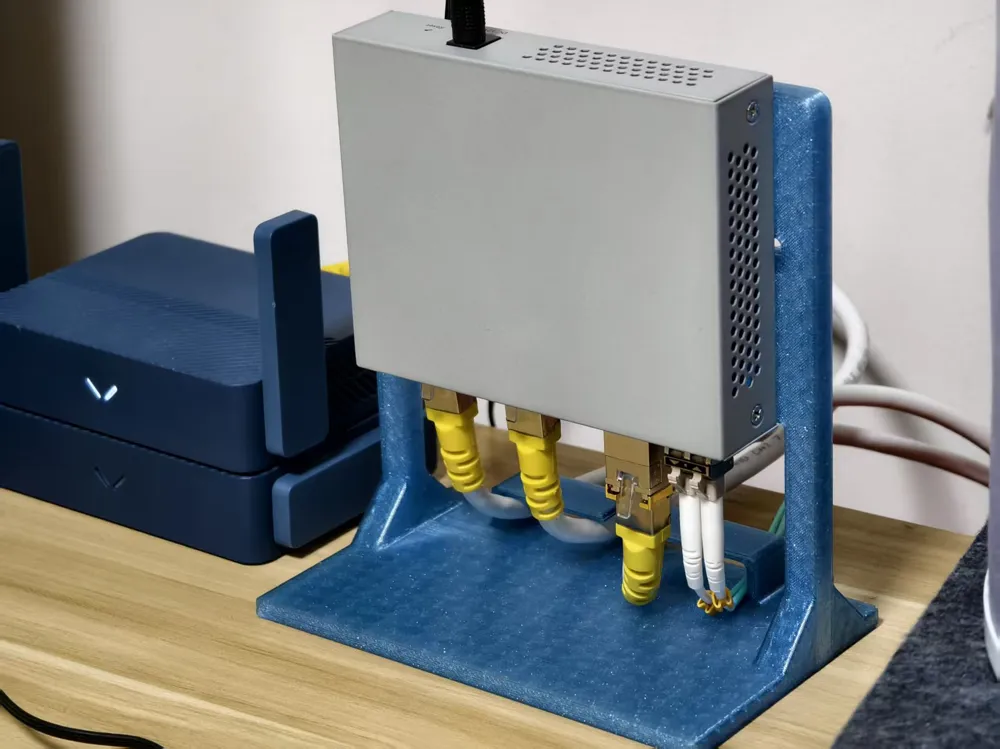
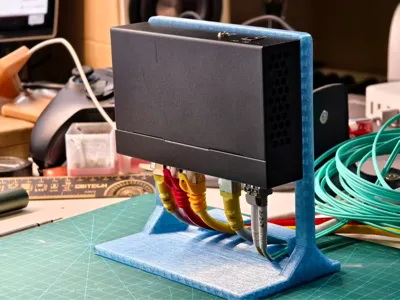
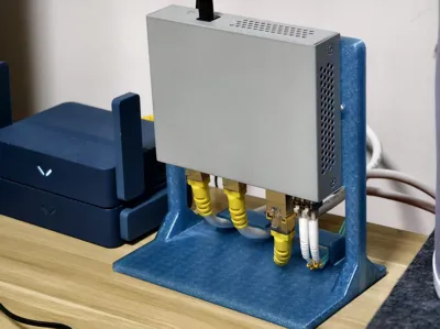
* **Bottom Clearance Space**: The bottom of the stand has ample space for cable management. It is recommended to install the switch with network ports facing downwards. Network cables can pass through the hollow space, which is both aesthetically pleasing and prevents excessive bending of network cables and RJ45 connectors.
* **Filament Recommendation**: It is recommended to print using PETG material (translucent blue shown in the effect image). PETG offers better toughness and structural strength, perfectly capable of supporting the downward external force from heavy network cables.
---
Enjoy your cable management! If you like this design, please give a five-star review (⭐⭐⭐⭐⭐) on MakerWorld and share your 3D printed photos!
This is an assembly guide for the universal desktop switch stand, designed to fit switches with wall-mount hole spacing of 25mm to 55mm.
Before assembly, please prepare the following hardware (which may be included in your kit):
| Part Name | Specification | Qty | Description |
| :--- | :--- | :--- | :--- |
| **Flat Head Screw** | M4 x 14 mm | 2 | Main mounting screws |
| **Nylon Lock Nut** | M4 | 2 | Used to set the gap for the wall-mount hole |
| **Standard Hex Nut** | M4 | 2 | Used to lock the screws from the back of the stand |
---
## 🛠️ Step-by-Step Assembly Instructions
### Step 1: Pre-assemble the Mounting Screws
1. Thread one **M4 Nylon Lock Nut** onto each **M4 x 14mm Flat Head Screw**.
2. **Crucial Step:** Leave a **2 to 3 mm gap** between the screw head and the lock nut. This gap is necessary for the screw head to slot securely into the switch's wall-mount keyholes.
> 💡 *Tip: Nylon lock nuts can be stiff. Use a small wrench or pliers to hold them while turning the screw with a screwdriver.*
### Step 2: Attach Screws to the Switch
1. Insert the heads of both pre-assembled screws into the keyholes on the back of your switch.
2. Slide the screws into the narrow section of the keyholes to lock them securely in place.
### Step 3: Mount to the Stand
1. Guide the remaining exposed threads (the part behind the lock nuts) through the **two horizontal slots (tracks)** on the front of the 3D-printed stand.
2. Slide the switch horizontally along the tracks to center it or place it in your preferred position.
### Step 4: Lock and Secure from the Back
1. Holding the switch in place, screw the **M4 Standard Hex Nuts** onto the exposed threads on the **back of the stand**.
2. Tighten the nuts. The switch will now be securely clamped to the stand with no wobble.
---
## 💡 Cable Management & Design Details
* **Bottom Clearance:** The bottom opening of the stand is designed with ample clearance for RJ45 connectors and fiber cables, preventing sharp bends and protecting your cable boots.
* **Filament Recommendation:** Printed beautifully in PETG (translucent blue shown in photos), providing great structural strength and flexural endurance for heavy network cables.
---
Enjoy your neat and organized desktop setup! If you like this model, please leave a ⭐⭐⭐⭐⭐ review and share your print photos on MakerWorld!
License

You may create derivative works based on this object, provided that all such derivative works are published exclusively on the MakerWorld platform and include proper attribution to the original creator. You may not share, upload, host, distribute, or publish this object—or any derivative work of this object—on any other digital platform, marketplace, or distribution channel. Commercial use of this object and any derivative works is strictly prohibited. This includes, but is not limited to, selling, renting, sublicensing, or using the object in any context in which you receive monetary compensation or other financial benefits.


Comment & Rating (0)