
DIY Handheld Thermal Camera - ESP32 Heatmap
Print Profile(1)
Bill of Materials

Description
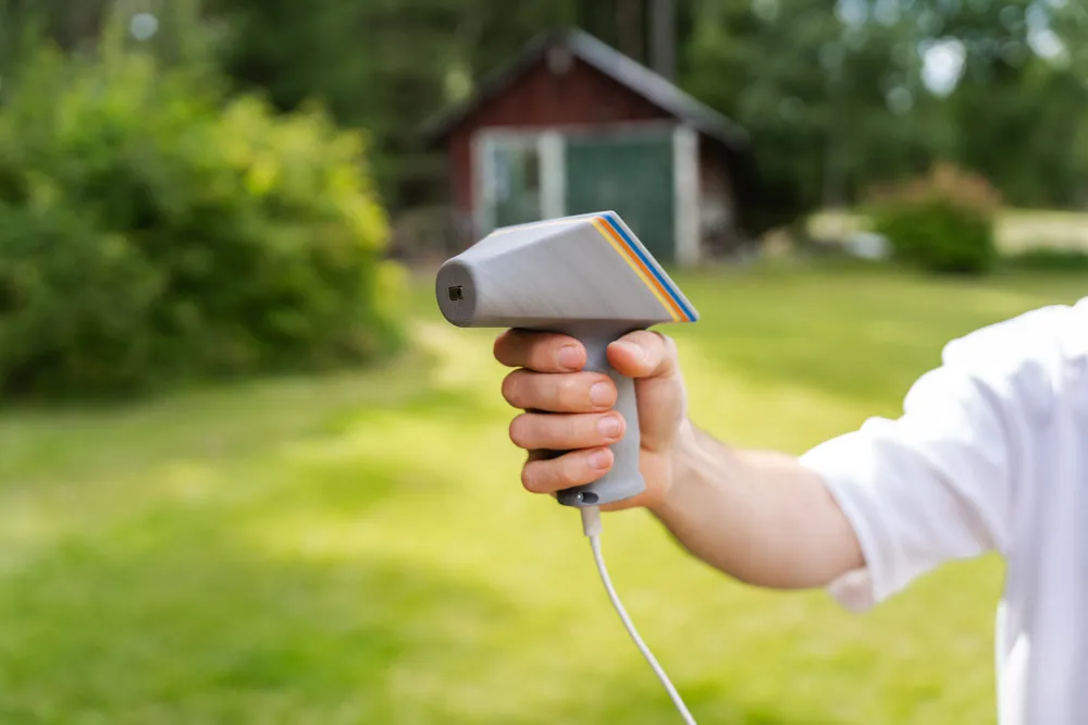
DIY Handheld Thermal Camera – ESP32 + AMG8833 + 8×8 LED Matrix

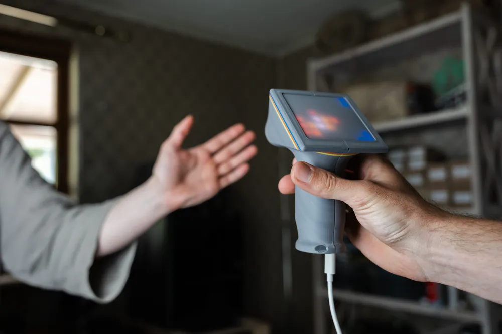

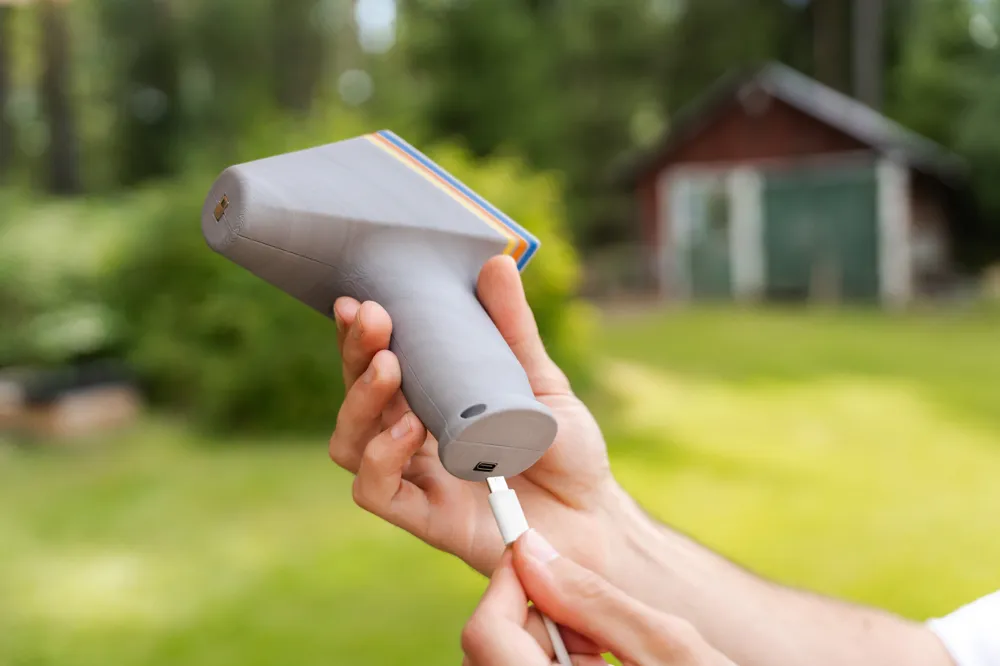
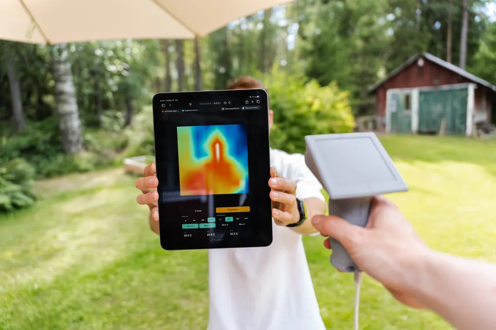
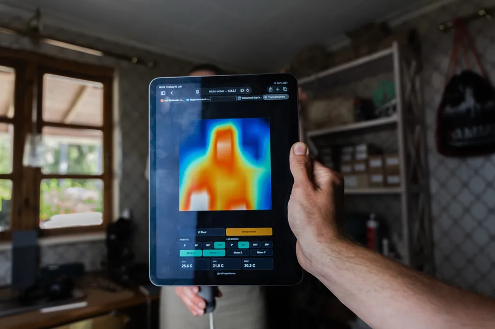
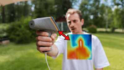
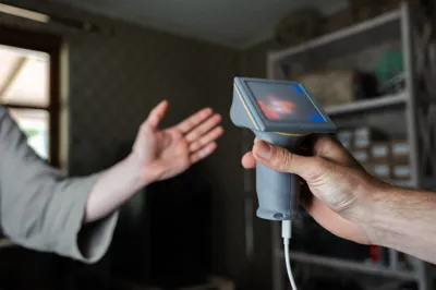
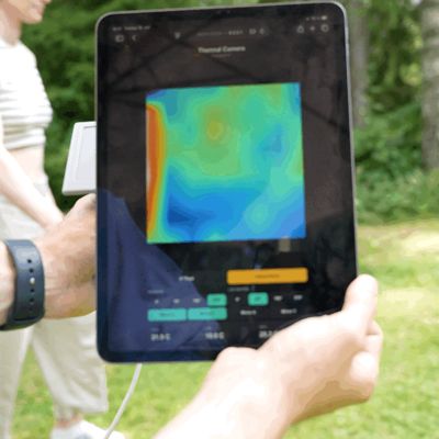
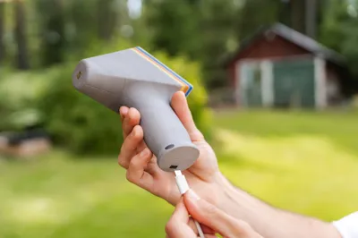
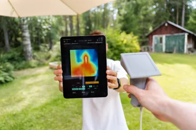
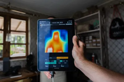
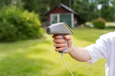
With this project, you can build a small DIY thermal camera. It is based on an ESP32, an AMG8833 8×8 thermal sensor, and a WS2812B 8×8 LED matrix. The camera displays temperature differences directly on the LED matrix. Additionally, the ESP32 creates its own Wi-Fi network through which the thermal image data can also be displayed in a browser
Assembly Video
Watch assembly video on YouTube
Required Components
| Component | Quantity | Link |
|---|---|---|
| ESP32 Dev Board | 1× | click me |
| AMG8833 / Grid-EYE Thermal Sensor | 1× | click me |
| WS2812B 8×8 LED-Matrix | 1× | click me |
| Thin Wires / Dupont Cables | several | click me |
| Screw M3 x 6mm | 8x | click me |
Pinout
| Connection | ESP32 Pin | Component Pin |
|---|---|---|
| LED Data Line | GPIO 5 | DIN of WS2812B Matrix |
| LED Power Supply | 5V / VIN | 5V of WS2812B Matrix |
| LED GND | GND | GND of WS2812B Matrix |
| AMG8833 Data Line | GPIO 21 | SDA |
| AMG8833 Clock Line | GPIO 22 | SCL |
| AMG8833 Power Supply | 3V3 | VIN / VCC |
| AMG8833 GND | GND | GND |
Important: All GND lines must be connected to each other. This includes ESP32-GND, AMG8833-GND, and LED Matrix-GND
The LED matrix is powered by 5V. The AMG8833 should be powered by 3.3V
Prepare Firmware
For the firmware, you need the Arduino IDE or PlatformIO
Required Libraries:
- Adafruit AMG88xx
- FastLED
- ESP32 Board Package
After uploading, the ESP32 automatically starts its own Wi-Fi network
Wi-Fi Name:
ThermalCamera
Then connect to this Wi-Fi network with your phone or laptop and open this address in your browser:
http://4.3.2.1
There, the thermal image display will be shown. You can also rotate or mirror the orientation of the web view and the LED matrix directly in the browser
Important Code Parameters
You can adjust these values in the upper part of the code:
| Parameter | Default | Meaning |
|---|---|---|
| LED_PIN | 5 | Data pin of the WS2812B LED matrix |
| NUM_LEDS | 64 | Number of LEDs, 64 for 8×8 |
| I2C_SDA | 21 | SDA pin for the AMG8833 |
| I2C_SCL | 22 | SCL pin for the AMG8833 |
| SERPENTINE | false | Set to true if your matrix is wired in a serpentine pattern |
| ORIGIN_TOP_LEFT | true | Determines if the first LED is top left |
| FLIP_X | false | Mirrors the LED output left/right |
| FLIP_Y | false | Mirrors the LED output top/bottom |
| BRIGHTNESS | 16 | Brightness of the LEDs, 0–255 |
| MAX_MILLIAMPS | 450 | Current limit for the LED matrix |
| FRAME_MS | 100 | Frame rate, 100 ms corresponds to approx 10 FPS |
| DEADBAND_C | 3.0 | Temperature range around the reference temperature that remains black |
| MIN_SIGNAL_C | 2.5 | Minimum scaling, reduces flickering at uniform temperature |
| REF_SMOOTH | 0.90 | Smoothing of the reference temperature |
| PRINT_EVERY_N | 5 | Outputs every fifth frame in the serial monitor |
| AP_SSID | ThermalCamera | Name of the Wi-Fi network created by the ESP32 |
Adjust Sensitivity
If you want to see more temperature details:
#define DEADBAND_C 2.0f
If only strong heat sources should be visible:
#define DEADBAND_C 4.0f
If the display flickers:
#define REF_SMOOTH 0.95f
If the response should be faster:
#define REF_SMOOTH 0.80f
LED Matrix Orientation
If the image is rotated or mirrored, there are two options:
- Rotate or mirror the LED matrix directly in the browser at http://4.3.2.1
- Adjust these values in the code:
#define SERPENTINE false #define ORIGIN_TOP_LEFT true #define FLIP_X false #define FLIP_Y false
Many 8×8 LED matrices are constructed differently. If the display is not right, first change SERPENTINE. Then test FLIP_X or FLIP_Y if needed
Assembly
- Print housing parts
- Place ESP32, AMG8833, and LED matrix into the housing for a test fit
- Connect AMG8833 with 3V3, GND, SDA, and SCL
- Connect LED matrix with 5V, GND, and GPIO 5
- Connect all GND lines together
- Upload firmware to the ESP32
- Before closing, test if the sensor and LEDs are working
- Insert AMG8833 so that the sensor faces forward
- Place LED matrix behind the front opening or diffuser
- Route cables neatly and close the housing
- Connect to the Wi-Fi network ThermalCamera and open http://4.3.2.1
- If necessary, adjust the display orientation in the browser
Troubleshooting
| Problem | Possible Cause / Solution |
|---|---|
| AMG8833 not found | SDA/SCL swapped, incorrect voltage, GND missing |
| LED matrix remains dark | Check 5V/GND, check DIN, observe direction arrow of the matrix |
| ESP32 keeps restarting | Power supply too weak, reduce brightness |
| Image is mirrored | Adjust FLIP_X, FLIP_Y or browser settings |
| Image is rotated by 90° | Change rotation in the browser |
| Wi-Fi does not appear | Restart ESP32, re-upload code, check serial monitor |
| Browser shows no data | Connect to the Wi-Fi network ThermalCamera and open http://4.3.2.1 |
Notes
This thermal camera is a DIY maker project and not a calibrated measuring device. The display is suitable for visualizing temperature differences, but not for precise or safety-critical measurements
The LED matrix can draw a relatively large amount of current depending on the brightness. For USB operation, low brightness is advisable. Therefore, the brightness in the code is set to 16 by default and the current limit to 450 mA
Boost Me (for free)
Thank you!!! :)
Documentation (1)
License

You shall not share, sub-license, sell, rent, host, transfer, or distribute in any way the digital or 3D printed versions of this object, nor any other derivative work of this object in its digital or physical format (including - but not limited to - remixes of this object, and hosting on other digital platforms). The objects may not be used without permission in any way whatsoever in which you charge money, or collect fees.


Comment & Rating (2)