
Electroplating Rotary
Print Profile(1)
Bill of Materials
- heat inserts 3mm x 5:
- 9v battery x 1:
- 9v battery push on connector x 1:
- slide power switch x 1:
- KY-040 rotary encoder x 1:
- LM2596 buck converter x 1:
- Seeed XIAO ESP32-C6 x 1:
- ULN2003 stepper driver x 1:
- 28BYJ-48 stepper motor x 1:
Description
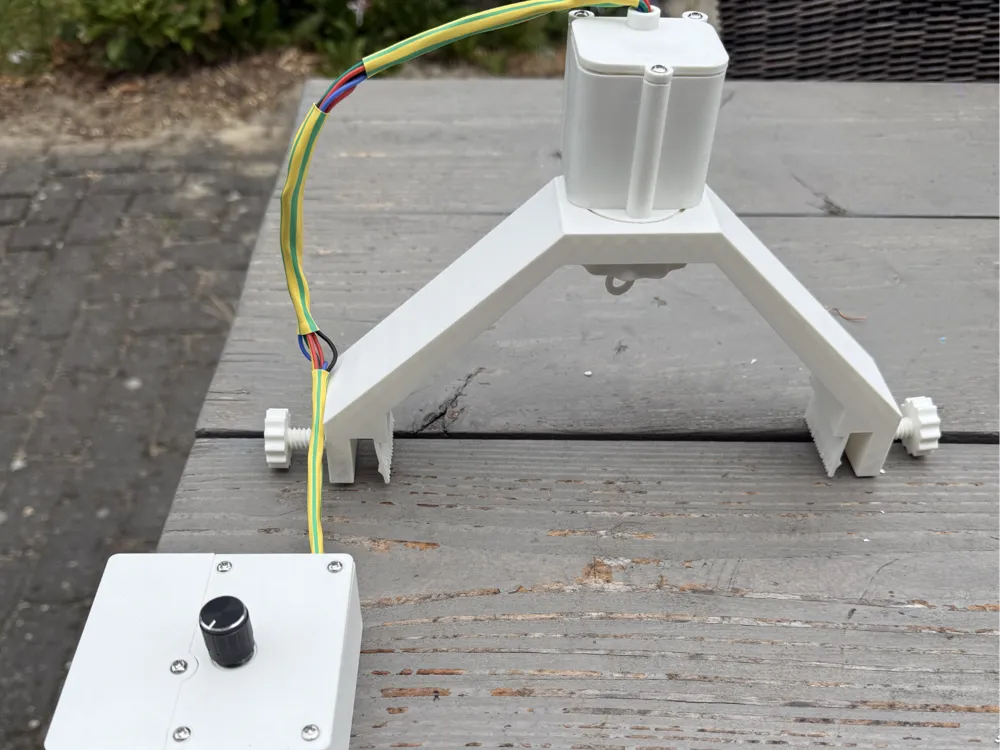
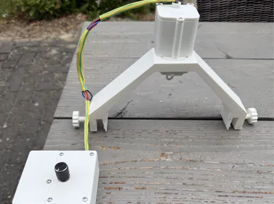
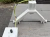
I wanted to electroplate my models and investigated online for suiting models. Found none that I was happy with. So I decided to design and build my own. The design consists of three main parts:
1) the motor assembly
2) the controlbox
3) the arc bridge assembly
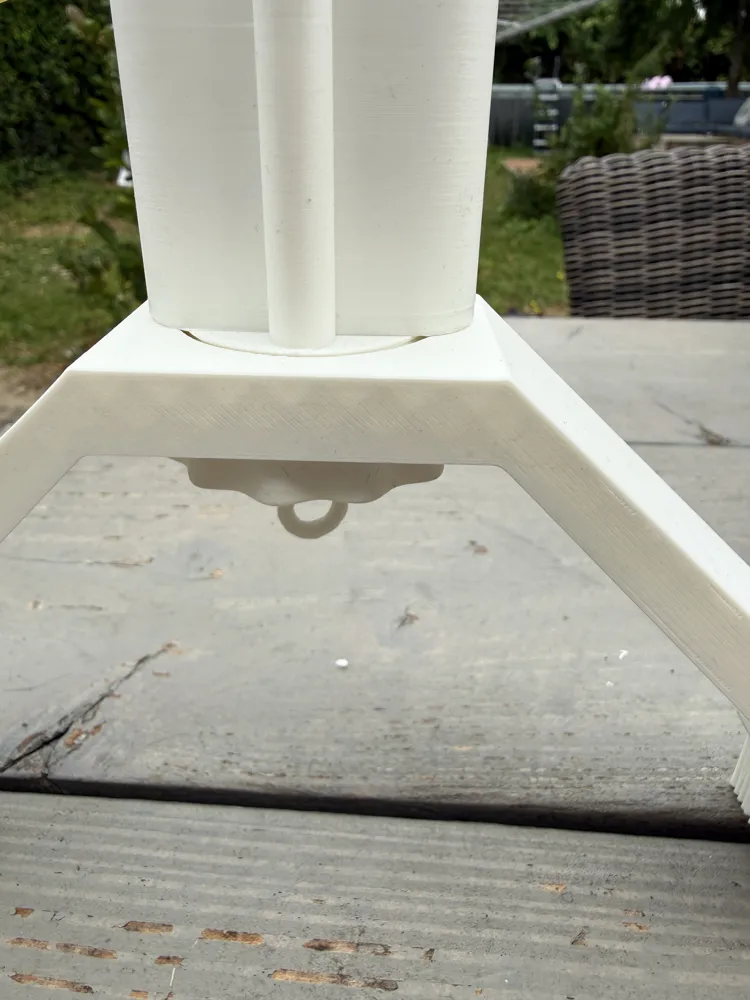
The motor assembly is designed so it can easily be fitted on different sized arc bridges, because not all containers have the same width/height requirements. I will share the dimensions of the current container i used, orderable off amazon. If you have another container, I will share the SCAD file as well, so you can easily adapt the width to your needs. Keep in mind that the min dia is always the width of the motormount plate and standoffs to the side of the container. The motor assembly itself houses the stepper (28BYJ-48) and the ULN2003 motor driver board.
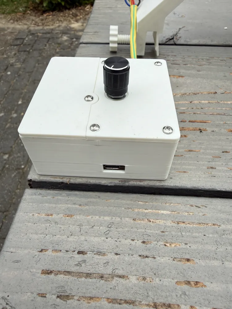
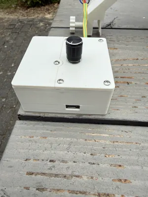
The controlbox has a couple of easy to acquire and solder components: an ESP32 board (i used a SEED XIAO ESP32-C6, very small board), a LM2596 buck converter, a rotary encoder (KY-040) to control the speed, a battery and an on/off switch. I will share the scheme here as well. The ESP firmware will also be shared (rename the main.c.txt to main.c)
IMPORTANT NOTE; make sure to trim your buck convertor to 5v before connecting anything to it, otherwise it may be set too high and you will fry your electronics
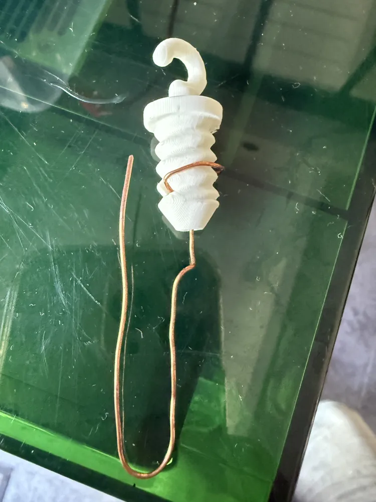
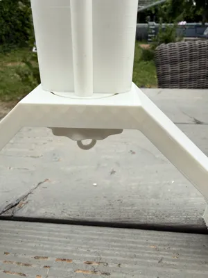
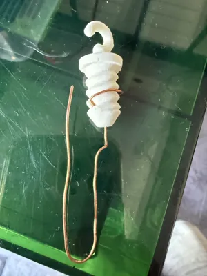
The arc bridge is pretty straightforward; it clamps on to the side of the container (dont overdo it, just keeps it from moving around) and comes with a nut to secure the motor assembly in place. I also designed a model hook that allows a straight copper wire down into the bath, by easily sticking the wire in from below, where it exits on the side and you can loop it around the rough thread of the hook. this is a 10/10 connection to your model. Moreover; this allows you to prep and test your hookup before you connect it to the hook of the rotary and allows for multiple models to be prepared in parallel.
In functional terms; the device is powered either through usb or through a 9v block in the compartment of the control box, it's wired to prefer the USB power when available. The movement is started by pushing in the rotary encoder button, that controls start/stop movement. then turning the knob controls the speed of movement. The movement is designed as an oscillator; it turns 1,25 times and then reverses that movement. This is to make sure your connecting wire (to the negative lead) doesnt get looped (ruining your electrical connection).
I added the whole setup in one .3mf on two plates. enjoy and let me know if you have questions or are happy with your build !
Documentation (2)
License



Comment & Rating (0)