
Print Profile(1)
Description
3-Piece Mechanical Latch & Shifter Mechanism
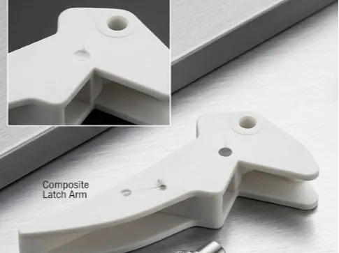
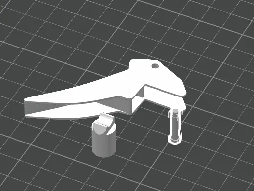
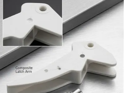
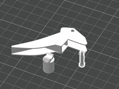
This model is a functional latch or pawl mechanism designed for robotics, automation, and kinematics projects. The assembly consists of three independent parts optimized for clean 3D printing, with ideal tolerances for fluid movement after assembly.
It is perfect as an educational component, for integration into mechanical sorting systems, or personalized 3D printing projects.
Included Components (Bill of Materials)
- Main Latch Arm: Pivoting upper piece with pronounced hook geometry for locking/retention. It features an open rear clevis with concentric holes to house the axle and facilitate angular play.
- Actuator Piston: Vertical cylinder designed with a curved profile recess at its top to smoothly guide or mechanically interact with the arm's lower base.
- Pivot Hinge Pin: Precision shaft that connects the arm to its support or external base. It includes a knurled end for a firm grip and a retaining groove (circlip/e-clip slot) to prevent axial dislodgement during continuous use.
Suggested Print Settings (Bambu Studio)
To ensure the correct mechanical functioning of the parts and that the pin fits smoothly into the clevis, apply the following configuration:
- Ideal filament: PETG, PLA Tough or ABS/ASA (PETG or ABS significantly reduce mechanical friction wear at contact points).
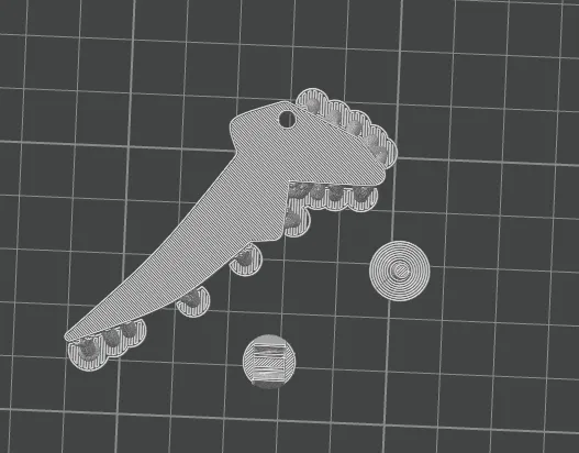
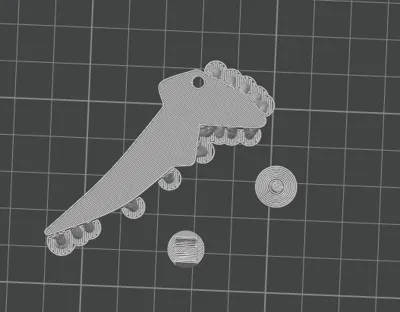
- Orientation on the build plate: * Print the Latch Arm resting on one of its flat side profiles.
- The Piston and Pin should be printed vertically (it is recommended to add a Brim of 5 mm to ensure bed adhesion due to their tall and narrow base).
- Layer height: 0.16 mm or 0.20 mm (fine resolution improves pin sliding and piston contact curves).
- Walls (Wall Loops): Minimum 3 or 4 perimeters to provide the necessary structural rigidity to the shafts.
- Infill: 20% - 30% (Gyroid type to support bidirectional forces).
License

You shall not share, sub-license, sell, rent, host, transfer, or distribute in any way the digital or 3D printed versions of this object, nor any other derivative work of this object in its digital or physical format (including - but not limited to - remixes of this object, and hosting on other digital platforms). The objects may not be used without permission in any way whatsoever in which you charge money, or collect fees.


Comment & Rating (0)