
Arcade Button Box
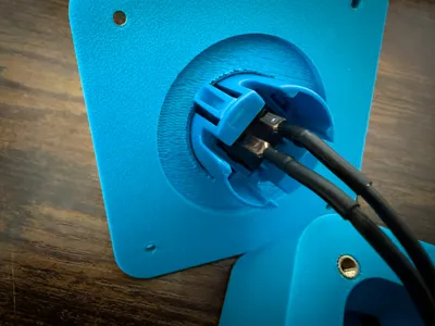
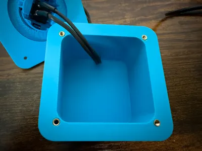
Print Profile(1)
Bill of Materials


- 2x 2.8mm Female Spade Connectors (Crimp terminals) x 1:
- 2-Core Wire / Speaker Wire x 1:
- 30mm 2-pin arcade button x 1:
Description
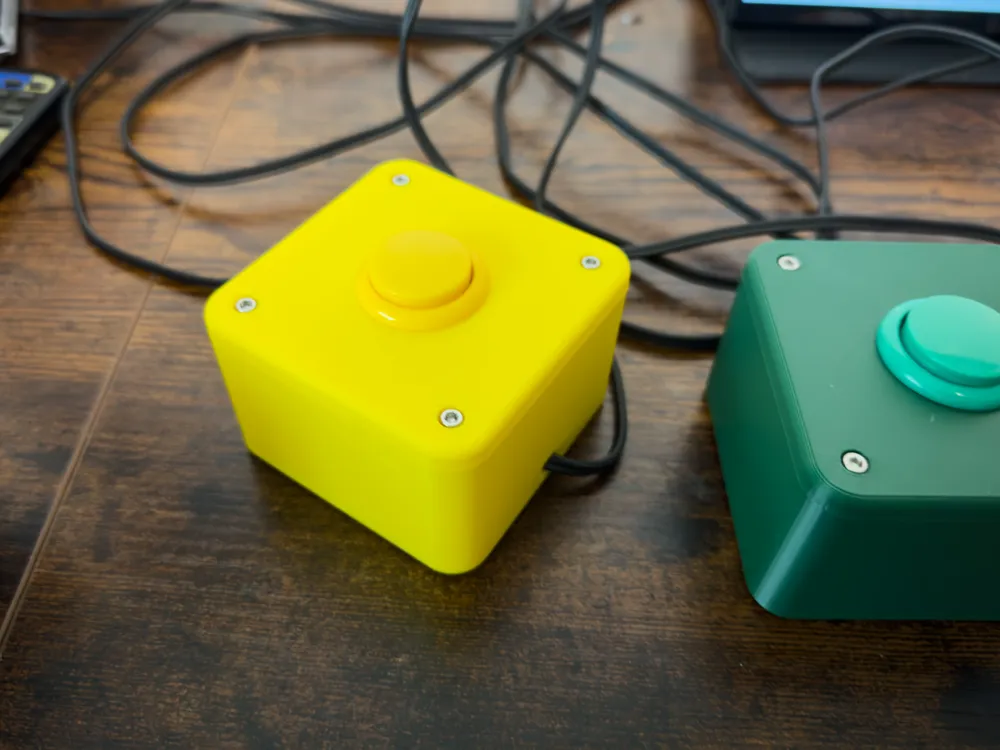
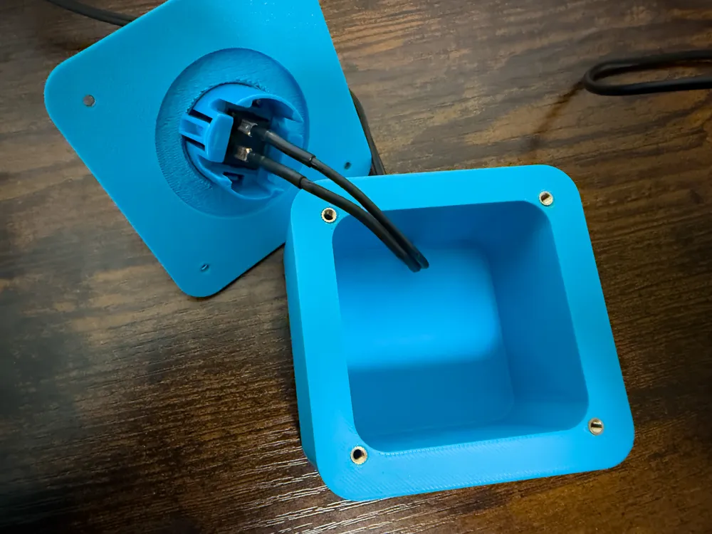
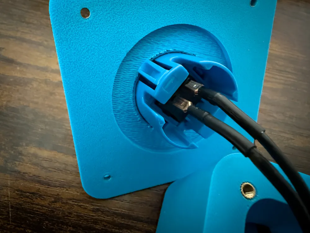
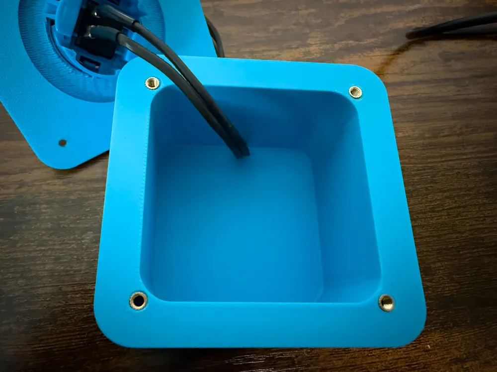
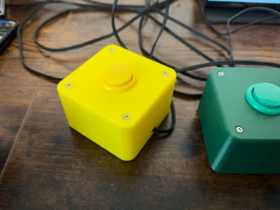
A sturdy and simple enclosure designed for 30mm snap-in arcade buttons (Sanwa-style or clones). The case features a 3mm top plate to ensure the snap-in mechanism locks securely, and a rear cable exit.
Features:
- Bore size: 30mm for standard arcade buttons.
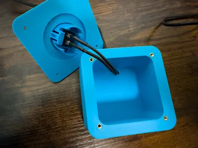
- Assembly: Uses M3 heat-set inserts for secure and repeatable assembly.
- Cable Management: Rear cutout for twin-core wires.
Use Cases:
- Custom trivia/quiz buzzers (e.g., connected to a Raspberry Pi/Arduino)
- DIY USB macro pads or PC controls
- Sim racing or flight simulator dashboards
Required Hardware (BOM):
- 1x 30mm Arcade Button (Snap-in style)
- 4x M3 Heat-Set Inserts (Bambu Lab, Ruthex or other)
- 4x M3 Screws
- 2-Core Wire / Speaker Wire
- 2x 2.8mm Female Spade Connectors (Crimp terminals)
Print Settings & Orientation:
- Material: PLA
- Infill: 15% Grid
- Walls: 2 Perimeters
- Print Profile vs. STL: The provided 3MF print profile is oriented with the top facing up and uses supports under the thinned button area. It also uses variable layer height for a cleaner top chamfer.
- Printing without supports: If you prefer to print without supports using the raw STLs, simply rotate the top cover 180 degrees (face down on the build plate) in your slicer.
My Setup (DIY Raspberry Pi Quiz System):
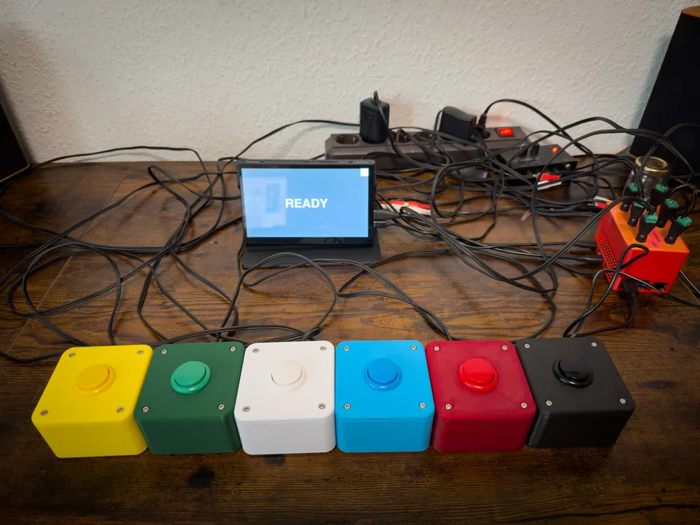
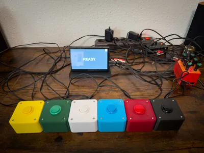
I originally designed these button boxes for my own custom trivia system. The buttons are wired to a Raspberry Pi 4 (any other model like a Zero 2W, 3, or 5 will work fine) using standard twin-core speaker wire.
Each button simply connects to one GPIO and one GND pin—polarity doesn't matter for these basic switches. To keep the wiring manageable and avoid soldering, I spliced in cheap DC barrel jacks with screw terminals. Alternatively, 3.5mm audio jacks or Wago connectors work great too.
You can easily add more buzzers by making them share GND pins; your only limit is the number of available GPIOs!
If you want to recreate this setup, you can find the Python code I wrote for the quiz logic here: 👉 https://gist.github.com/Gesichtsschnitzel/3a3deabf9ecb4bb2860c575168acfa32
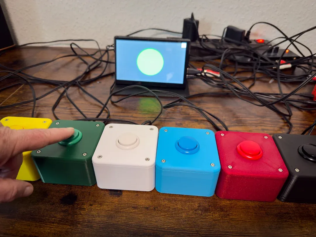
All the Buttons and a small 7" Display for displaying the fastest buzzer
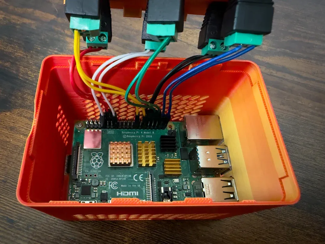
The wiring from the Raspberry to the DC-barrels
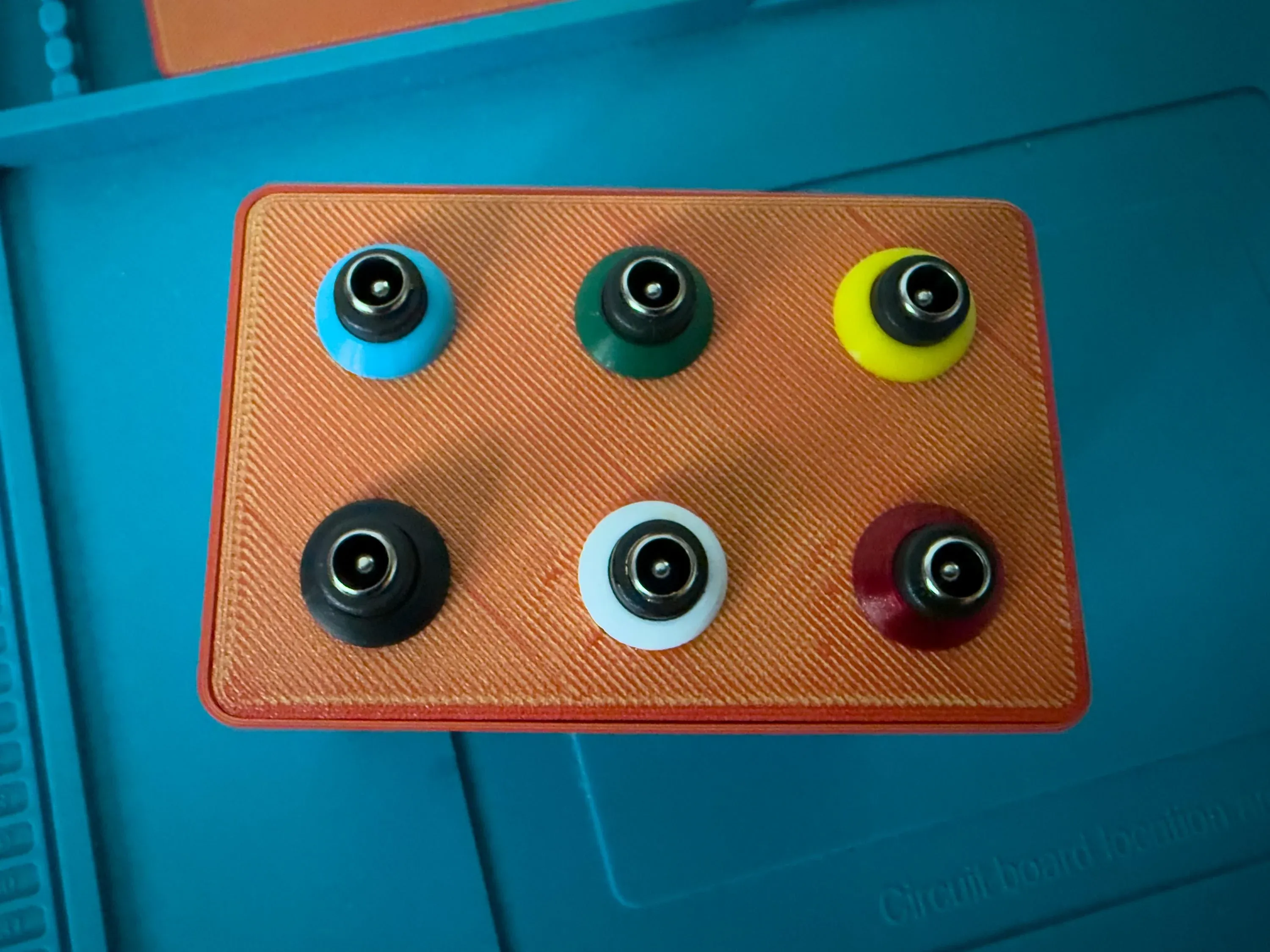
The top of a modified Raspberry enclusure
License

You shall not share, sub-license, sell, rent, host, transfer, or distribute in any way the digital or 3D printed versions of this object, nor any other derivative work of this object in its digital or physical format (including - but not limited to - remixes of this object, and hosting on other digital platforms). The objects may not be used without permission in any way whatsoever in which you charge money, or collect fees.


Comment & Rating (0)